
Method for making a cylinder

a technology of cylinders and cylinder bodies, applied in the field of making cylinders, can solve the problems of high manufacturing cost of cylinders and engines, costly processing machines, and known methods, and achieve the effect of rapid and cost-effective manufacture of cylinders

Inactive Publication Date: 2007-01-09
ANDREAS STIHL AG & CO KG
View PDF8 Cites 5 Cited by
  • Summary
  • Abstract
  • Description
  • Claims
  • Application Information

AI Technical Summary

Benefits of technology

[0005]It is an object of the invention to provide a method of the kind described above which makes possible a rapid and cost effective manufacture of the cylinder.
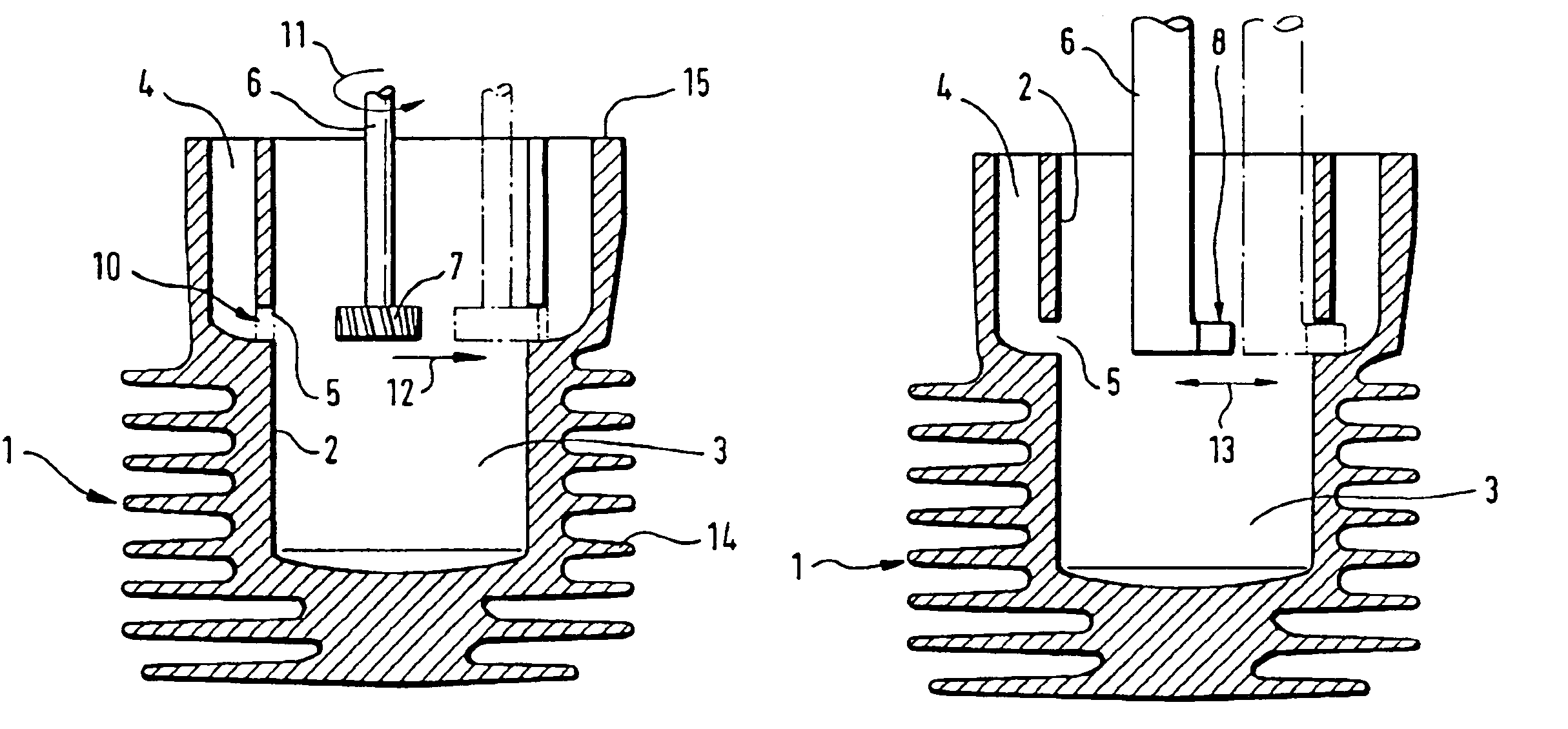
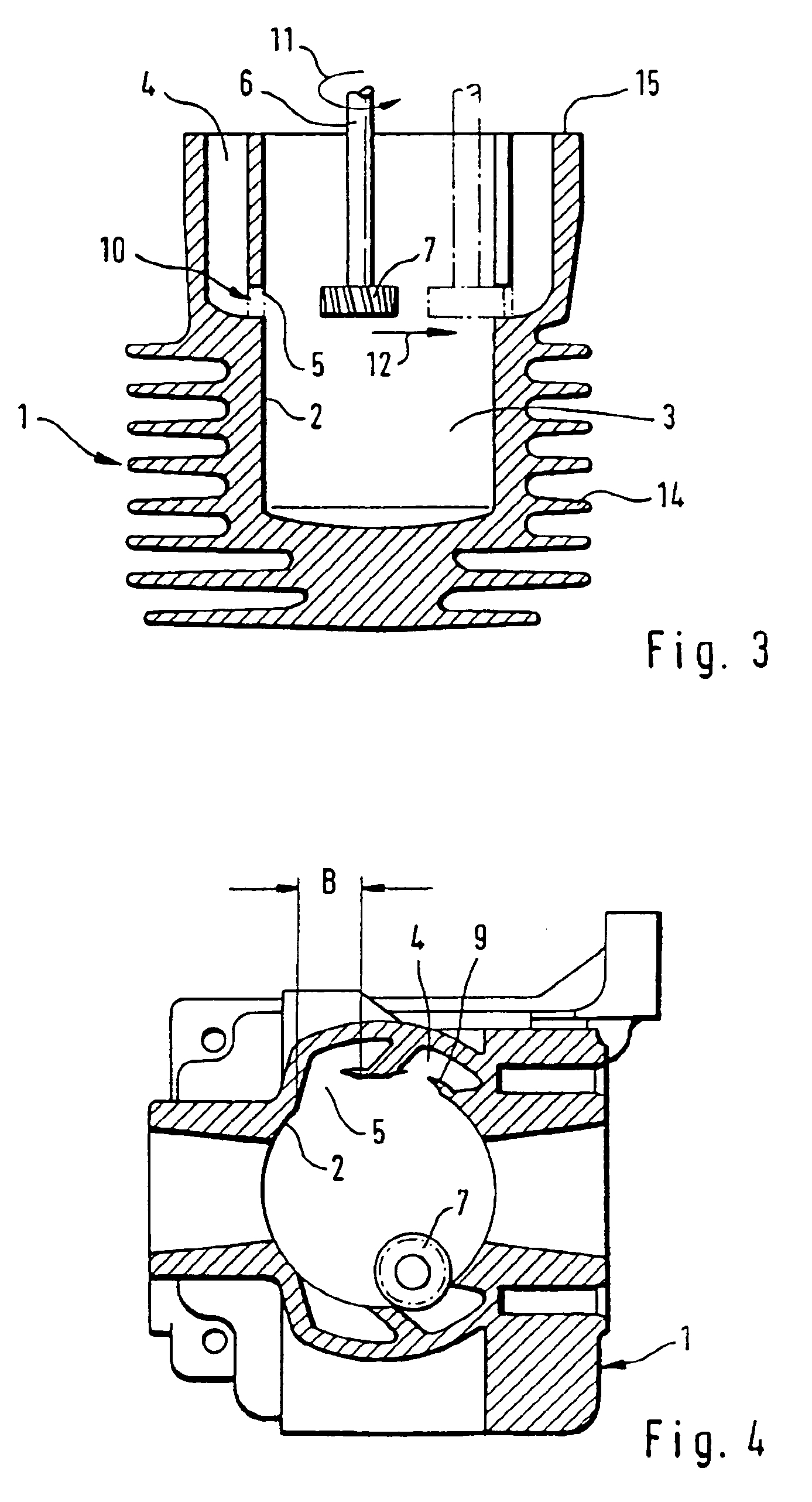
[0007]According to the invention, a cost-effective manufacture of the cylinder is achieved with a two-stage machining in the formation of the control window in the cast cylinder housing. In a first step, the cylinder wall is broken through in the intended location of the control window with a chip-removing tool with a rotating primary movement and, in a second step, the breakthrough is widened to the planned dimensions of the control window with a work tool having a preferably linear primary movement. In this way, a large part of the required material removal for cutting out the control window is carried out with a rotating primary movement with a cost-effective manufacturing method. Burrs remain from the rotating primary movement of the work tool in the first step and these burrs can be cleanly removed with a straight-line machining and the precise dimensions of the control window can be machined. The machining according to the invention in the second step can be cost effectively carried out preferably with a work tool having an especially straight-line primary movement and, as may be required, even with the same processing machine.
[0008]The combination according to the invention of two machining steps with a first rotating machining operation and thereafter the completion of the control window with another work tool makes possible a precise formation of the control window for each transfer channel with the manufacturing costs clearly reduced relative to the known method.
[0009]The breakthrough of the cylinder wall in the first step of forming the control window advantageously takes place by milling. A breakthrough can be formed with a dimension corresponding already to the intended elevation of the control window in axial direction of the cylinder when a side-milling cutter is used having the cutting width corresponding to the elevation. The machining of the control window in the cylinder wall can be further accelerated when the first machining step takes place with a work tool having a rotating primary movement up to a cut of the work tool into the cylinder wall corresponding to the intended width of the control window in the peripheral direction of the cylinder.
[0010]The second machining step takes place preferably with a tool having a linear primary movement, preferably, with a drilling tool and especially a broach or scraping tool. The tool to be guided linearly is aligned into a work position by a machine tool driving the work tool and is driven by the transverse feed movement of the machine tool in the primary movement direction. Preferably, the machining with the linear primary movement takes place with a rotatingly driven work spindle. The feed movement in the rotational operation of the spindle forms the primary movement of the tool in the linear movement. In this way, the first processing step with a rotating cutting movement and the linear primary movement in the second step can be carried out with the same machine tool and, in this way, the machining time is reduced with a very short changeover for the new work tool for the second machining step.

Problems solved by technology

The manufacture of cylinders with the known method, however, requires costly processing machines to effect a non-contact cutting out of the control windows in the cylinder wall.
In the manufacture of cylinders for small internal combustion engines such as those used in portable handheld work apparatus, the non-contact machining leads to high manufacturing costs of the cylinder and therefore of the engine.
This is especially unacceptable when manufacturing in large quantities.

Method used


Image

  • Method for making a cylinder
  • Method for making a cylinder
  • Method for making a cylinder

Examples


Embodiment Construction

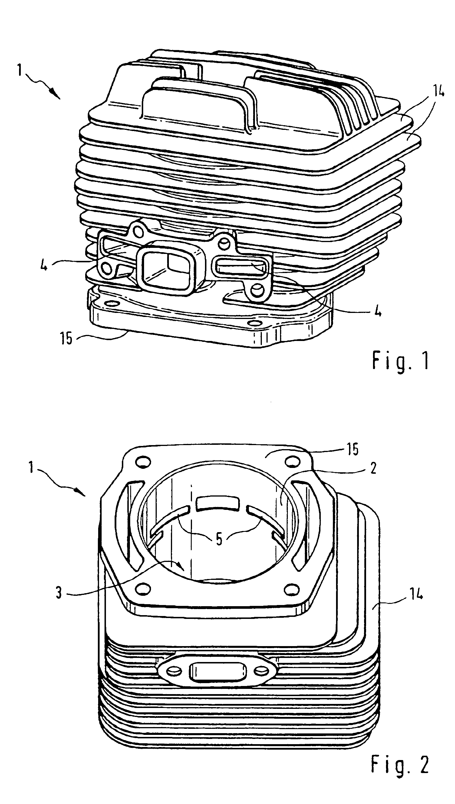
[0020]FIGS. 1 and 2 show a cylinder housing 1 for an internal combustion engine of a portable handheld work apparatus which is originally formed as a pressure die cast part and delimits with a cylinder wall 2 an interior space 3 for accommodating a reciprocating piston. The cylinder wall 2 is equipped with cooling ribs 14 on its outer side for air cooling the cylinder. The cylinder housing 1 is cast integrally and is open at one end for insertion of the reciprocating piston. The open end is configured with a planar flange 15 for connecting to an engine block. Control windows 5 are machined into the cylinder wall 2 and define the openings of transfer channels 4 into the interior space 3 of the cylinder and are opened and closed during operation of the engine for the purpose of a charge exchange by the reciprocating movement of the piston. Depending upon the type of construction of the engine, the transfer channels 4 can supply air or can be supplied with an air / fuel mixture from the ...


PUM

PropertyMeasurementUnit
thrustaaaaaaaaaa
attack angleaaaaaaaaaa
heightaaaaaaaaaa

Abstract

A cylinder housing (1) is cast with a cylinder wall (2) in the making of a cylinder for an internal combustion engine. The cylinder wall delimits an interior space (3) for accommodating a reciprocating piston and, thereafter, a control window (5) is machined into the cylinder wall (2) as an opening of a transfer channel (4) into the interior space (3). A two-stage machining for forming the control window (5) is provided in order to make possible a rapid and cost effective manufacture of the cylinder. In a first step with a work tool (7) having a rotating primary movement (11), a breakthrough (10) is machined into the cylinder wall (2) and, in a second step with a work tool, the breakthrough (10) is widened to the wanted dimensions of the control window (5).

Description

CROSS REFERENCE TO RELATED APPLICATIONS[0001]This application claims priority of German patent application no. 102 43 520.0, filed Sep. 19, 2002, the entire content of which is incorporated herein by reference.BACKGROUND OF THE INVENTION[0002]U.S. Pat. No. 6,041,499 discloses a method wherein a cylinder housing is cast having a cylinder wall which delimits an interior space for accommodating a reciprocating piston. The cylinder is provided for a two-stroke engine and therefore transfer channels enclosed in the cylinder wall are provided. The combustion chamber is delimited by the piston. The supply of the combustion chamber in the cylinder with the fuel mixture or air is ensured via the transfer channels in a manner known per se. The transfer channel runs essentially axially in the cylinder wall and, to connect the transfer channel to the interior of the cylinder, a radial control window is provided in the cylinder wall which is cyclically covered and again cleared by the stroke pis...

Claims


Application Information

Patent Timeline
Patent Type & Authority Patents(United States)
IPC IPC(8): B23P11/00B23P13/00B23P13/02B23P15/00F02F1/10F02F1/22F16J10/00
CPCB23P13/00B23P15/00F02F1/22F02F1/10Y10T29/49995Y10T29/4927
Inventor BROCKEL, KLAUSFISCHER, HARTMUTROSSKAMP, HEIKOAMEND, HELMARKLARIC, IGOR
Owner ANDREAS STIHL AG & CO KG
Learn More