Electric actuator

a technology of electric actuators and actuators, which is applied in the direction of mechanical equipment, mechanical energy handling, and mechanical devices, can solve the problems of complex centering alignment operation and inability to reduce the size of electric actuators in the axial direction, and achieve the effect of reducing the size and assembling

Inactive Publication Date: 2007-01-09
SMC CORP
View PDF24 Cites 14 Cited by
  • Summary
  • Abstract
  • Description
  • Claims
  • Application Information

AI Technical Summary

Benefits of technology

[0009]A general object of the present invention is to provide an electric actuator which makes it possible to reduce the size in the axial direction and miniaturize the...

Problems solved by technology

Thus, it is impossible to reduce a size of the electric actuator in the...

Method used


Image

  • Electric actuator
  • Electric actuator
  • Electric actuator

Examples


Embodiment Construction

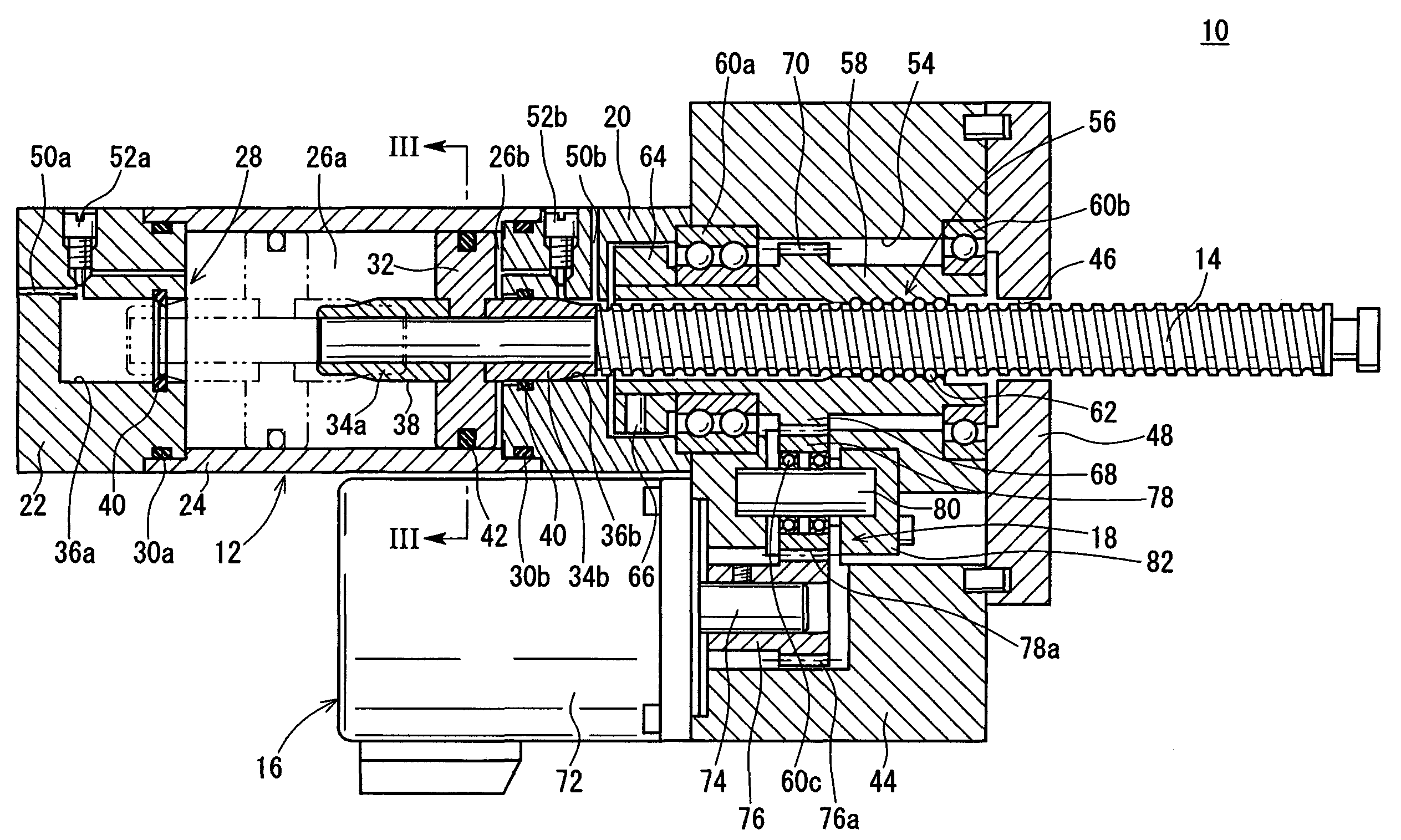
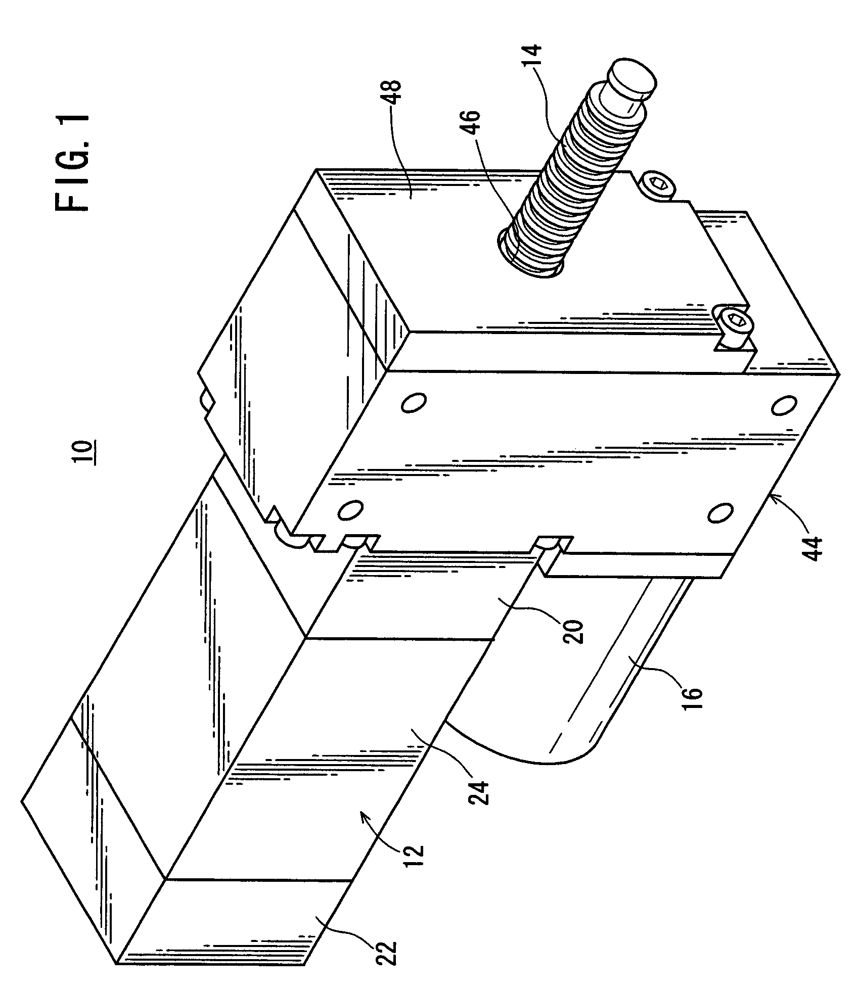
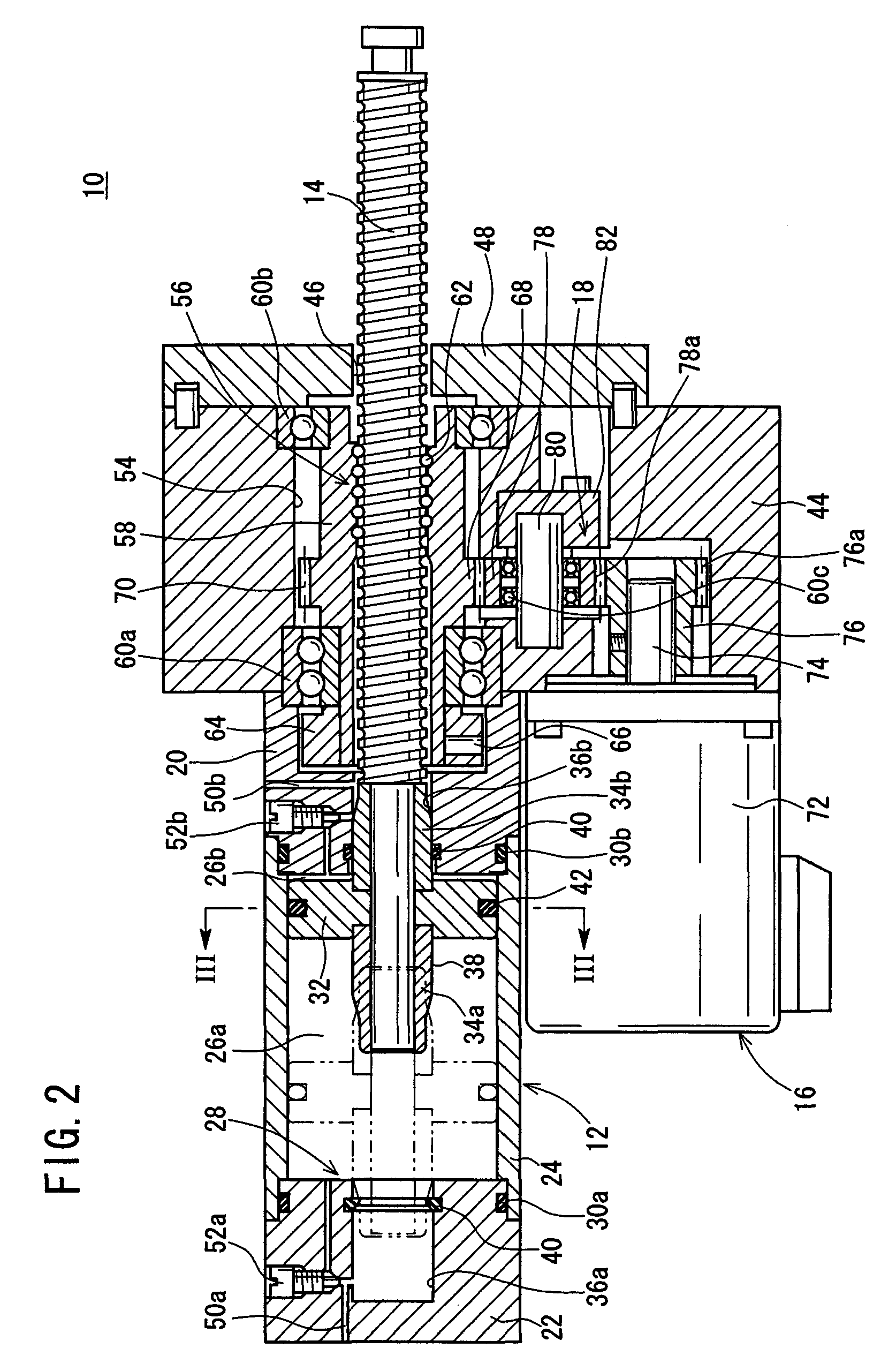
[0020]With reference to FIGS. 1 and 2, reference numeral 10 indicates an electric actuator according to an embodiment of the present invention.

[0021]The electric actuator 10 comprises an actuator body 12 which functions as a main body unit, a ball spline shaft (feed screw shaft) 14 which is provided movably back and forth toward the outside from one end surface of the actuator body 12, a rotary driving source 16 which is arranged substantially in parallel to the axis of the ball spline shaft 14, and a gear mechanism 18 (see FIG. 2) which transmits the rotary driving force of the rotary driving source 16 to the ball spline shaft 14.

[0022]The actuator body 12 includes a cushion mechanism 28 which has closed cushion chambers 26a, 26b formed therein by connecting a tube member 24 between a rod cover 20 disposed on one end and a head cover 22 disposed on the other end. Seal members 30b, 30a for air-tightness are installed to connecting portions between the tube member 24 and the rod cove...


PUM


Abstract

An electric actuator comprises a gear mechanism which transmits the rotary driving force of a rotary driving source, and a ball spline mechanism which includes a ball spline shaft provided movably back and forth from a connecting block to the outside and which converts a rotary motion transmitted by the gear mechanism into a rectilinear motion. The electric actuator has a ball spline nut which is externally fitted to the ball spline shaft to be meshed with the gear mechanism and which is integrally formed with a gear section having a plurality of teeth arranged circumferentially about the gear section.

Description

BACKGROUND OF THE INVENTION[0001]1. Field of the Invention[0002]The present invention relates to an electric actuator provided with a ball spline shaft which is movable back and forth from an actuator body to the outside, driven by a rotary driving source.[0003]2. Description of the Related Art[0004]Electric actuators have been used, for example, in order to transport workpieces or position workpieces. Such an electric actuator is provided with a motor, a ball screw shaft which is linearly and substantially coaxially connected with a drive shaft of the motor by a coupling member, and a slider which is displaceable in the axial direction by a nut member externally fitted to the ball screw shaft.[0005]In this arrangement, the motor is driven and rotated, and the rotary driving force thereof is transmitted to the ball screw shaft. Accordingly, the slider is displaced by the nut member which is screw-engaged with the ball screw shaft.[0006]However, in the conventional electric actuator,...

Claims


Application Information

Patent Timeline
IPC IPC(8): F16H25/24F16H25/20F16H25/22H02K7/06
CPCF16H25/2204H02K7/06Y10T74/18688Y10T74/18704Y10T74/18576Y10T74/18592
Inventor NAGAI, SHIGEKAZUSAITOH, AKIOYUMIBA, HIROSHI
Owner SMC CORP
Why Eureka
Try Eureka