Power switching system for acoustic apparatus

a power switching and acoustic equipment technology, applied in the direction of speed-changing/reversing arrangements, instruments, gear, etc., can solve the problems of unfavorable acoustic equipment, unfavorable acoustic equipment, and complicated drive power switching systems, and achieve the effect of smooth fitting

Active Publication Date: 2007-01-09
TANASHIN DENKI CO
View PDF6 Cites 3 Cited by
  • Summary
  • Abstract
  • Description
  • Claims
  • Application Information

AI Technical Summary

Benefits of technology

[0014]In the drive power switching system according to the first aspect of the invention, the rotational resistance between the first and second gears can be converted to the rocking force of the rocking member. Also, since the driven gear is brought into mesh with the gear on the rocking end side with rotation in the wedging direction, the rocking member can obtain rocking force from the gear on the rocking end side. Thus, the rocking member can be given high rocking power without provision of any special member. With the provision of the two driven gears on the rocking member, it is possible to set a large inter-axis distance between the first and second supporting axes of both the first and second driven gears, and the design can be given a degree of freedom.
[0016]According to the third aspect of the invention, the second gear in the rotation prohibition state is held with the dedendum directed to the addendum of the driven gears when the addendum of the driven gears are separated from the dedendum of the second gear. Thus, conversely when the addendum of the driven gear approaches the second gear, the addendum of the driven gear can be smoothly fitted in the dedendum of the second gear.

Problems solved by technology

Therefore, the drive power switching system is complicated in construction, and also an undesired extra light rocking load is added to the drive power transfer route.
Therefore, the drive power switching requires a certain interval of time.

Method used


Image

  • Power switching system for acoustic apparatus
  • Power switching system for acoustic apparatus
  • Power switching system for acoustic apparatus

Examples


Embodiment Construction

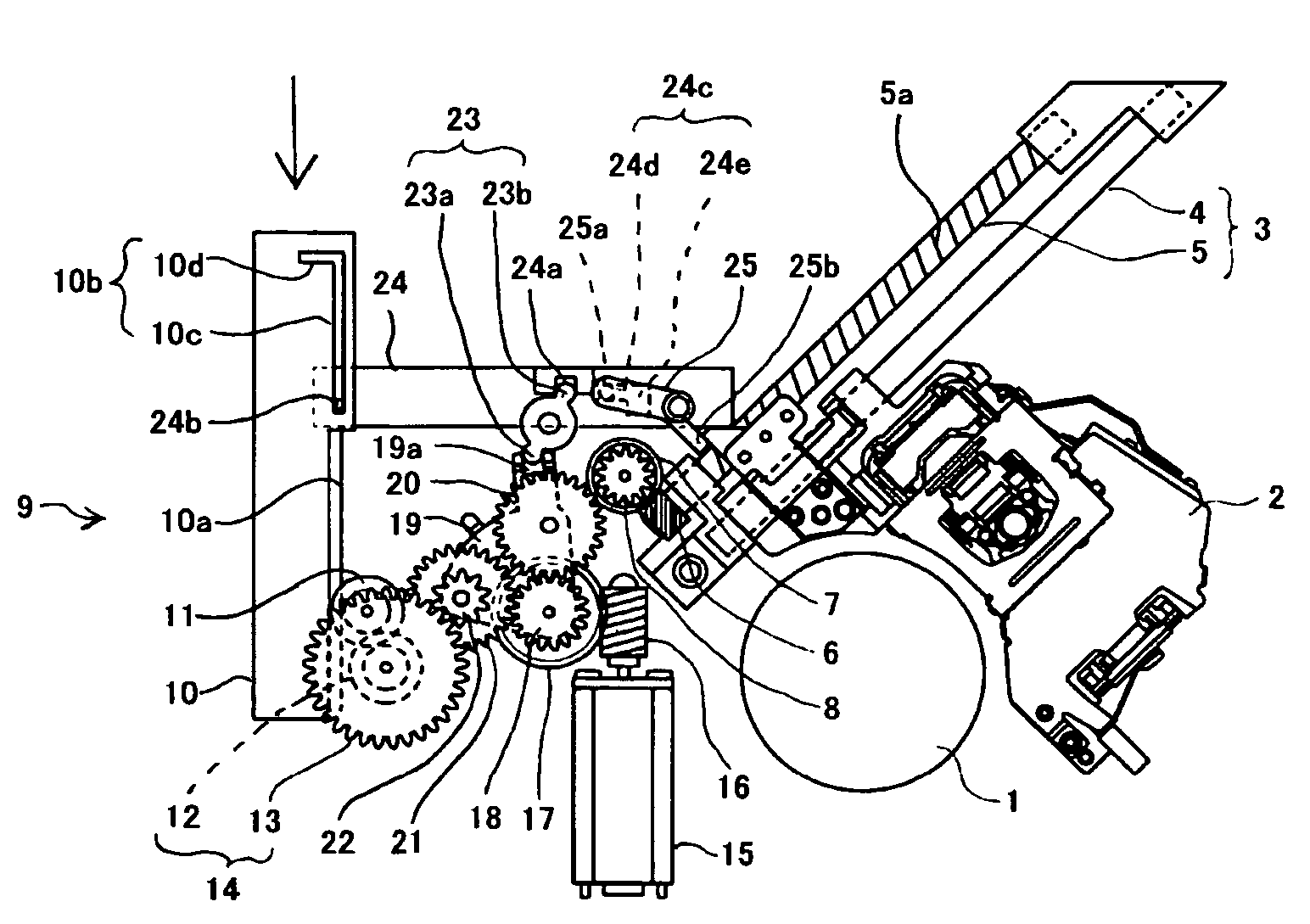
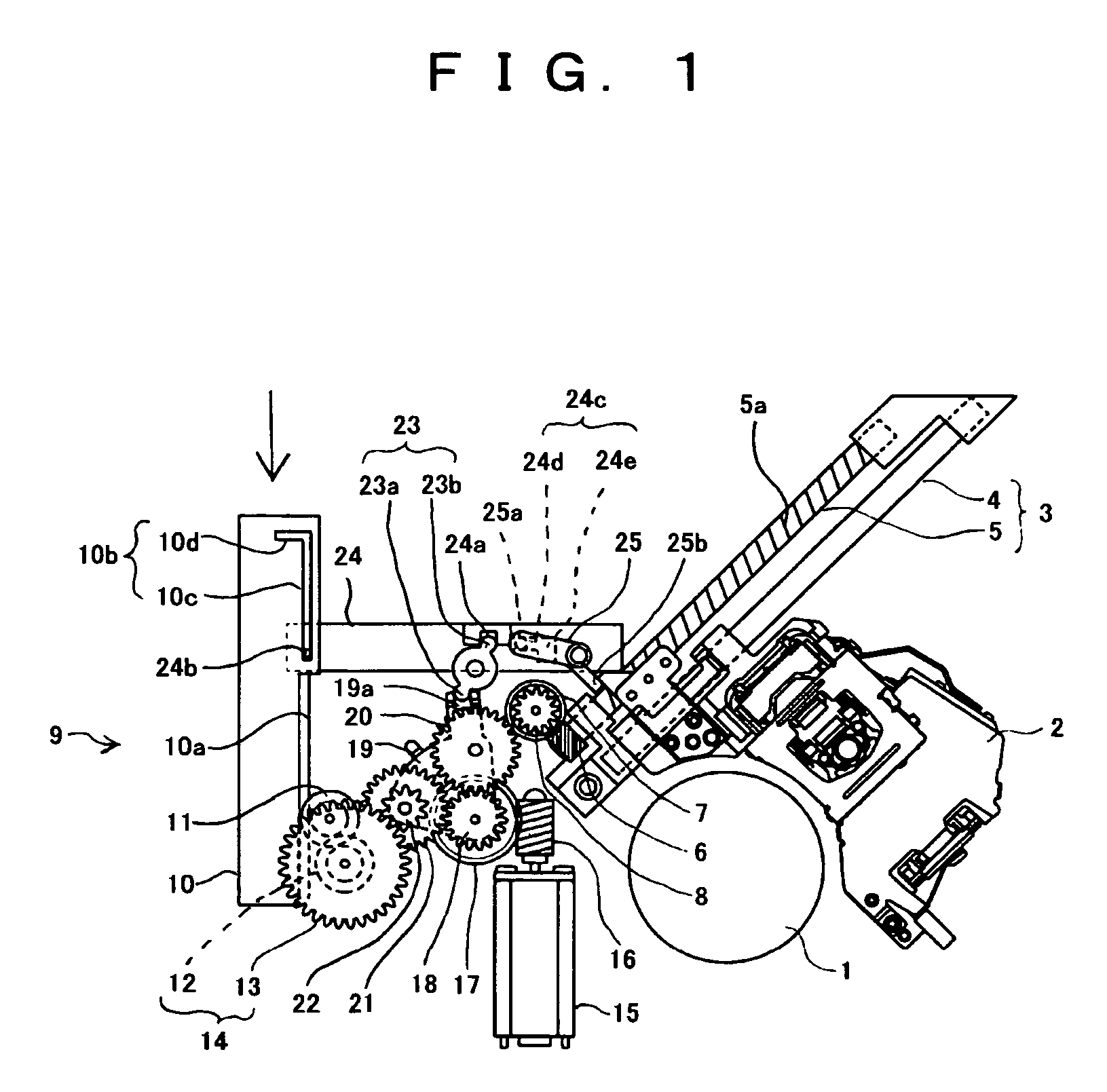
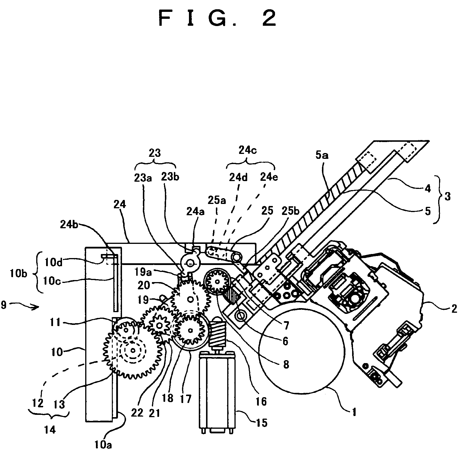
[0024]In the drive power switching system for an acoustic apparatus according to the invention, the inter-axis distance between a first and a second gear, namely between a first and second supporting axes of both the first and second gears is set to a length permitting driven gears to be meshed with both the first and second gears during rocking of the driven gears with rocking of a rocking member.

[0025]Assuming now that the acoustic apparatus according to the invention is a disc player, the drive power switching device used for the apparatus will be described with reference to FIG. 1. Referring to FIG. 1, a turntable motor 1 for driving a disc is disposed on a base member (not shown) at the center thereof. A pick-up 2 for playing a disc is disposed on a base member (not shown) such that it can be automatically advanced and retreated from a position close to the turntable motor 1 towards the disk edge by a pick-up drive mechanism 3 (i.e., first mechanism). The pick-up drive mechanis...


PUM

PropertyMeasurementUnit
rotation transmissionaaaaaaaaaa
lengthaaaaaaaaaa
rotationaaaaaaaaaa

Abstract

It is sought to simplify the arrangement of the drive power switching system for an acoustic apparatus, thus permitting immediate switching of the drive power. A drive power switching system comprises driven gears always in mesh with a main drive gear located between a first and a second gear and a rocking member rotatably supporting the driven gears. The inter-axis distance between the axes of rotation of the first and second gears, is set to a length, in which the driven gears can be meshed with both the first and second gears as they are revolved together with the revolution of the rocking member.

Description

BACKGROUND OF THE INVENTION[0001]1. Field of the Invention[0002]This invention relates to a power switching system for an acoustic apparatus for switching the drive power transmission such that driven gears meshing with a main drive gear are selectively brought into mesh with a first or a second gear with switching of the direction of rotation of the main drive gear.[0003]2. Description of the Prior Art[0004]In an acoustic apparatus, the drive power transmission route from the motor is selectively switched to either a first or a second gear by switching the direction of rotation of the motor. More specifically, a main drive gear rotated by the motor is disposed between the first and second gears, the driven gear which is always in mesh with the main drive gear is supported on a rocking member, and the driven gear is caused to rock together with the rocking member according to the direction of rotation of the main drive gear, thus selectively transmitting the drive power of the main ...

Claims


Application Information

Patent Timeline
Patent Type & Authority Patents(United States)
IPC IPC(8): F16H3/34F16H37/06F16H1/20G11B15/44G11B17/035G11B17/04G11B21/02
CPCG11B15/444G11B17/04F16H1/203Y10T74/192Y10T74/19367Y10T74/19358
Inventor YAMANAKA, TAKASHI
Owner TANASHIN DENKI CO
Why Eureka
Try Eureka