Teat cup take off

a milking machine and automatic technology, applied in the field of automatic milking and milking machines, can solve the problems of pain and injury, loss of milk production, loss of profit, etc., and achieve the effects of reducing pain and injury, and gentle treatment of milking animals

Inactive Publication Date: 2007-01-09
DELAVAL HLDG AB
View PDF12 Cites 6 Cited by
  • Summary
  • Abstract
  • Description
  • Claims
  • Application Information

AI Technical Summary

Benefits of technology

[0014]An advantage of the present invention is that a precise determination of the end of milk flow can be made for each teat independently.
[0015]A further advantage is that initiation of teat cup take off can be made precisely for each individual teat with regards to the end of milk flow for the respective teat.
[0016]Yet a further advantage is that a gentle treatment of a milking animal is achieved while keeping milk yield high.
[0017]Further characteristics of the invention and advantages thereof will be evident from the following detailed

Problems solved by technology

This naturally meant that a substantial part of the heard were over-milked, i.e. the teat cups were not removed in due time, resulting in pain and injury for these animals, while another significant part were under-milked, resulting in lost milk production and thus lost profit.
Since the milk flow and / or milk quantity is measured by a flow or quantity meter downstream of the teat and not measured at the teat cup, there will be a time delay between the actual ending of the milk flow and the measurement of decreased milk flow, resulting in some over-milking even for the last quarter.
However, the problem with the time delay between actual milk flow end and measured milk flow end still prevails.
Even though the system improves the situation, by both caring for the animal as well as allow for drawing as much milk as possible, the regulation will not be optimal, since the measurement of the milk flow is delayed from the actual milk flow changes due to the milk flow meter being positioned away from the teat.

Method used


Image

  • Teat cup take off
  • Teat cup take off
  • Teat cup take off

Examples


Embodiment Construction

[0023]In the following description, for purposes of explanation and not limitation, specific details are set forth, such as particular techniques and applications in order to provide a thorough understanding of the present invention. However, it will be apparent to one skilled in the art that the present invention may be practiced in other embodiments that depart from these specific details. In other instances, detailed descriptions of well-known methods and apparatuses are omitted so as not to obscure the description of the present invention with unnecessary details.

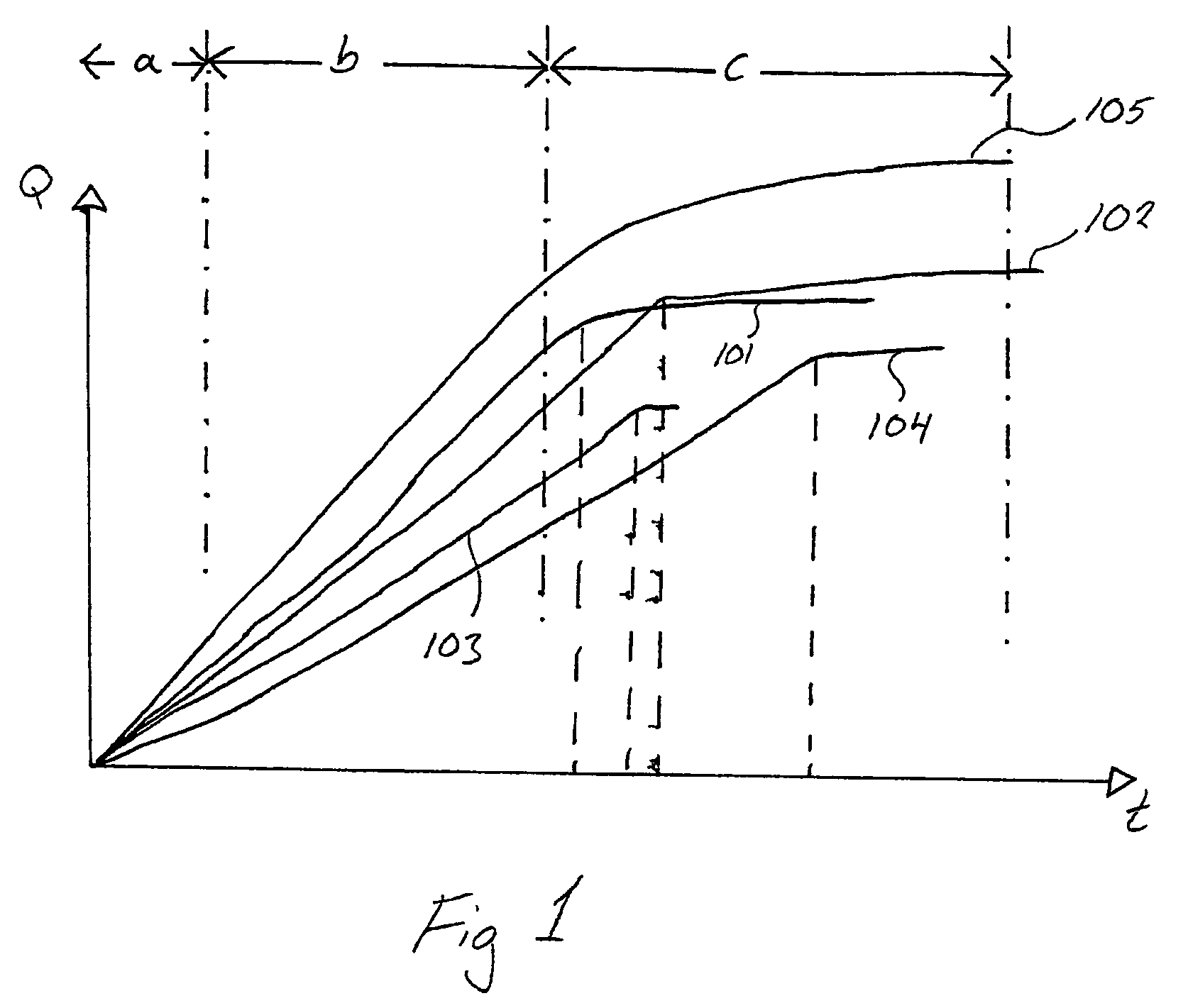
[0024]FIG. 1 shows a schematic diagram over the milk yield for each individual teat 101, 102, 103 and 104, respectively, as well as for the combine milk yield for all teats together 105. The milking sequence can be divided into three phases, a first relatively short phase a where milk flow increases, a second phase b with a relatively constant milk flow and a third phase c with declining milk flow. The different phases ...


PUM


Abstract

The present invention relates to a method and a milking machine comprising at least one teat cup for application to a teat of an animal to be milked, a teat cup liner, mounted in said teat cup, defining a teat receiving space inside said liner, and a pulsating chamber between said liner and said teat cup, said liner having a teat receiving end portion, a vacuum source for applying a vacuum level to the teat receiving space for drawing milk from said animal, a pulsator for application of a pulsating vacuum to the pulsating chamber for moving the teat cup liner between a closed position and an open position, thereby massaging said teat of said animal, and a vacuum sensor for sensing the vacuum level in said teat receiving end portion. The invention is further characterized in that said milking machine is arranged to initiated take off of said at least one teat cup, if a vacuum level sensed by said vacuum sensor indicates that the vacuum level in said teat receiving end portion is rapidly increasing.

Description

TECHNICAL FIELD[0001]The present invention relates to a method for automatic milking and a milking machine. More specifically, the present invention relates to a method and a milking machine for initiating take off of teat cups from an animal.BACKGROUND OF THE INVENTION[0002]In automatic milking systems the take off of teat cups has been automated for some time. Early systems for initiating take off were solely based on a timer. When the timer ran out, the teat cups were removed. The time had to be set as an average milking time for the whole herd of milking animals. This naturally meant that a substantial part of the heard were over-milked, i.e. the teat cups were not removed in due time, resulting in pain and injury for these animals, while another significant part were under-milked, resulting in lost milk production and thus lost profit.[0003]To avoid the problems mentioned above, the take off is initiated, in more recent milking machines, based on the milk flow, the amount of dr...

Claims


Application Information

Patent Timeline
Patent Type & Authority Patents(United States)
IPC IPC(8): A01J5/00A01J5/007
CPCA01J5/007
Inventor INNINGS, LARS
Owner DELAVAL HLDG AB
Why Eureka
Try Eureka