Fastener for fixing a prosthesis, and device for delivering this fastener

a technology for fixing prostheses and fasteners, which is applied in the direction of prosthesis, prosthesis, application, etc., can solve the problems of unfavorable meniscus repairing, lack of inability to ensure intimate contact of prosthetic components, so as to achieve the effect of increasing traction

Inactive Publication Date: 2007-01-09
SOFRADIM PROD SAS
View PDF16 Cites 131 Cited by
  • Summary
  • Abstract
  • Description
  • Claims
  • Application Information

AI Technical Summary

Benefits of technology

[0021]By virtue of the invention, the fastener can be inserted completely into said tube, with said immobilizing element directed toward the distal end of this tube and said anchoring element directed toward the proximal end of this tube. The latter forms a hollow implantation needle which makes it possible, from the direction of the anterior face of the anatomical support, to insert the fastener beyond the prosthetic component situated against the posterior face of this support; a partial extraction of the fastener from the tube makes it possible to release said immobilizing element, which can bear against the prosthetic component, then a return movement of the tube makes it possible to release the rest of the fastener and thus to implant the anchoring element at a depth which ensures intimate contact of the prosthetic component with the anatomical support.
[0022]Consequently, according to the invention, the device for delivering the fastener comprises said tube and the fastener mentioned above, the fastener being inserted into this tube with said immobilizing element directed toward the distal end of this tube and said anchoring element directed toward the proximal end of this tube; this tube comprises a pointed distal end having a lateral opening, and it is provided with a means for retention of the anchoring element below a threshold force; the lateral opening is dimensioned in such a way as to allow extraction of said immobilizing element from the tube when the fastener is pushed into the tube in the proximal to distal direction, and the retention means is positioned in such a way that it ensures retention of the anchoring element in the tube when the immobilizing element is thus extracted from the tube; said retention means is such that, below said threshold force, it permits the retreat of the fastener with the tube and that, once the immobilizing element is bearing against the prosthetic component and the prosthetic component is pressed against the anatomical support, it requires an increased traction on the tube in order to release the anchoring element, thereby ensuring that this anchoring element has a depth of anchoring sufficient to guarantee that said prosthetic component is pressed sufficiently against said anatomical support.

Problems solved by technology

The fastener according to the above document is suitable for repairing a meniscus but could not be used to fix a planar prosthetic component, for example a parietal reinforcement, to an anatomical support, in particular an abdominal wall.
The reason is that this fastener with an elastically deformable linking rod and with immobilizing bars connected rigidly to this linking rod prohibits any insertion of said first immobilizing bar inside a tissue wall, and said elasticity is not adapted to such an anchoring.
The main disadvantage of the fastener according to said prior art document and of the device for delivering it is that they do not ensure intimate contact of the prosthetic component with the anatomical support, and intimate contact of this kind is, of course, fundamental for good tissue integration of said prosthetic component.
However, given the shape of the fastener, this deployment generates a certain retreat of the distal anchoring element relative to this depth, resulting in the aforementioned lack of intimate contact.
Moreover, the presence of the linking rod at the end of the distal anchoring element constitutes an obstacle to insertion of this distal anchoring element and can cause a certain amount of damage at the anchoring site, the consequence of which is to affect not only the depth of implantation of the distal anchoring element but also the strength of the anchoring obtained.
This, too, may result in said lack of intimate contact.

Method used


Image

  • Fastener for fixing a prosthesis, and device for delivering this fastener
  • Fastener for fixing a prosthesis, and device for delivering this fastener
  • Fastener for fixing a prosthesis, and device for delivering this fastener

Examples


Embodiment Construction

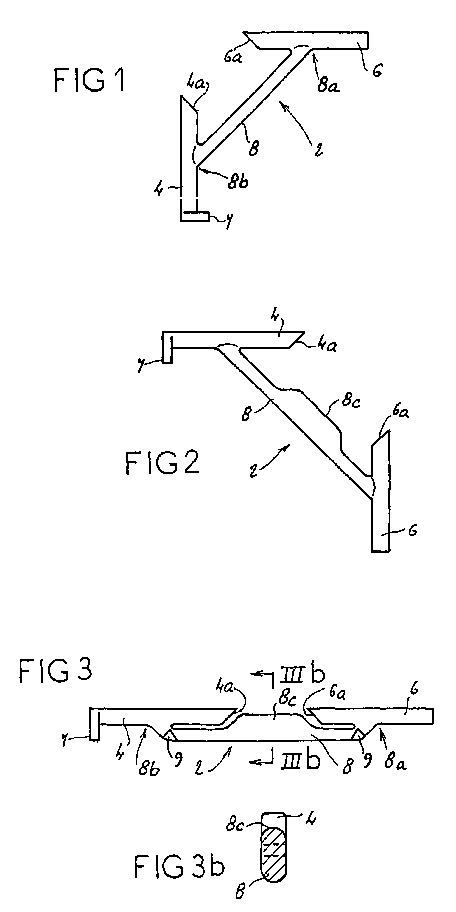
[0040]FIG. 1 shows, in the mold-release configuration, a fastener 2 comprising an anchoring element 4 and an immobilizing element 6 connected via a linking rod 8.

[0041]The latter is arranged between an intermediate point of connection 8b to the anchoring element 4 and an intermediate point of connection 8a to the immobilizing element 6.

[0042]According to FIG. 2, again in the mold-release configuration, the intermediate rod 8 has a bulge 8c substantially at its center. This bulge 8c consists of an excess thickness of material, of limited length relative to the length of the rod 8, and oriented and disposed only on the top of the core of the rod 8, and inside the fastener 2 in the tubular configuration of maximum stress shown in FIG. 3. As this figure shows, in the tubular configuration the bulge 8c fills or occupies the gap left free between the proximal end of the anchoring element and the distal end of the immobilizing element.

[0043]The fasteners 2 shown in FIGS. 1 and 2 have a con...


PUM


Abstract

A fastener including at least an element to be anchored in an anatomical support, at least a stop element relative to a planar prosthetic component to be fixed, and a linking rod is characterised in that the linking rod is rectilinear and the junction zones of the anchoring element and the stop element with the linking rod enable the fastener to adopt: a non-stressed stripping configuration; a maximum stress configuration, doubled up on itself, for example in a tubular configuration by complete insertion of the fastener into a tube, and a minimum stress configuration, wherein the respective directions of the stop element and the anchoring element form between them, for example in the same plane, an angle not greater than 90°.

Description

FIELD OF THE INVENTION[0001]The present invention relates to a fastener for fixing a prosthesis, for example of bioabsorbable material, used for fixing a planar prosthetic component in the human body relative to an anatomical support. It also relates to the device for delivering this fastener.BACKGROUND OF THE INVENTION[0002]According to the present invention, the terms used below in the description and the claims have the following meaning:[0003]“bioabsorbable material” is understood as a material which is decomposed and / or assimilated by and / or in the human or animal body;[0004]“anatomical support” is understood as non-mineralized human or animal support tissues.[0005]A prosthesis fastener intended for the repair of a fractured meniscus is known from EP-A-0 847 727. This fastener is made up of at least a first immobilizing bar intended to come into abutment against a meniscus fragment, at least one second immobilizing bar intended to come into abutment against another meniscus fra...

Claims


Application Information

Patent Timeline
Patent Type & Authority Patents(United States)
IPC IPC(8): A61D1/00A61B17/04A61B17/00A61B17/06A61B17/064A61B17/068A61B17/08A61B17/10
CPCA61B17/064A61B17/068A61B2017/00004A61B2017/0618A61B2017/0417A61B2017/0419A61B2017/0409
Inventor SGRO, JEAN-CLAUDETHERIN, MICHELORY, FRANCOIS-REGISBAILLY, PIERRE
Owner SOFRADIM PROD SAS
Why Eureka
Try Eureka