
Automatic power generation light-image fan device

a technology of automatic power generation and fan device, which is applied in the direction of static indicating device, machines/engines, instruments, etc., can solve the problems of heating-dispersing fans not having automatic power generation function, unable to provide light-image or color-mixing effects for generating better visual effects,

Inactive Publication Date: 2007-01-09
FANG YI FENG
View PDF11 Cites 35 Cited by
  • Summary
  • Abstract
  • Description
  • Claims
  • Application Information

AI Technical Summary

Benefits of technology

"The present invention provides a mechanism for a fan to have an automatic power generation function and control the light-emitting elements mounted on it for producing various twinkling light-image variations. This results in an effect of persistence of vision and different mixing-colors when the fan is rotating. The device includes a fan motor, a connector, an axle hole, a positioning magnet, a vane set, an automatic power generation component, a rectifier filter circuit, a circuit board, a programmable chip, light-emitting elements, a magnetic sensor, and a programmable chip that senses the position of the positioning magnet and counts the rotational speed of the fan motor. The programmable chip has an oscillator, a frequency selector, a ROM, a counter, a pattern memory, and a buffer integrated thereon."

Problems solved by technology

However, the above-mentioned light-emitting and luminous effects still cannot provide a light-image or color-mixing effects for generating better visual effects.
Moreover, the heating-dispersing fan does not have a function of automatic power generation.

Method used


Image

  • Automatic power generation light-image fan device
  • Automatic power generation light-image fan device
  • Automatic power generation light-image fan device

Examples


Embodiment Construction

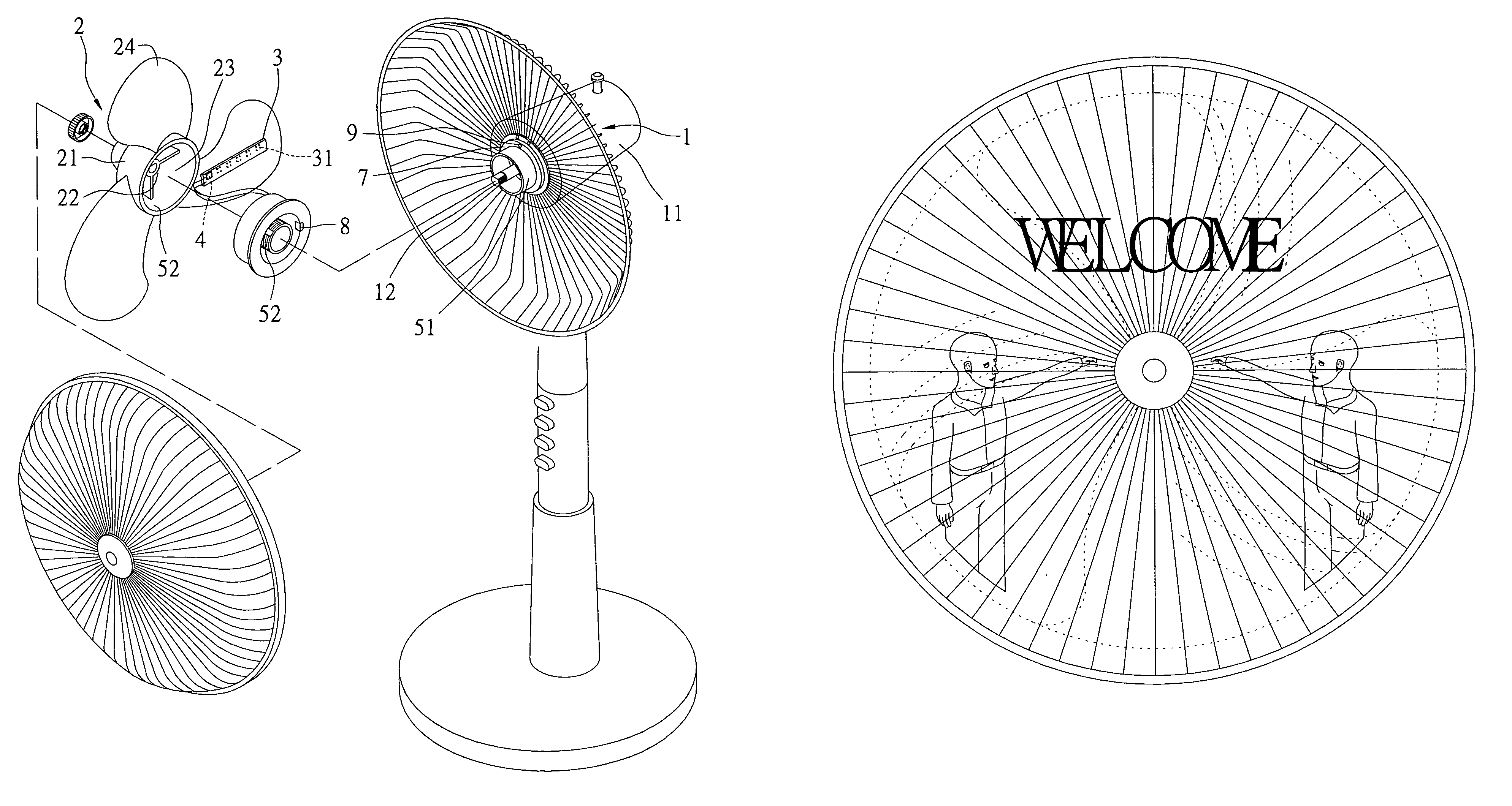
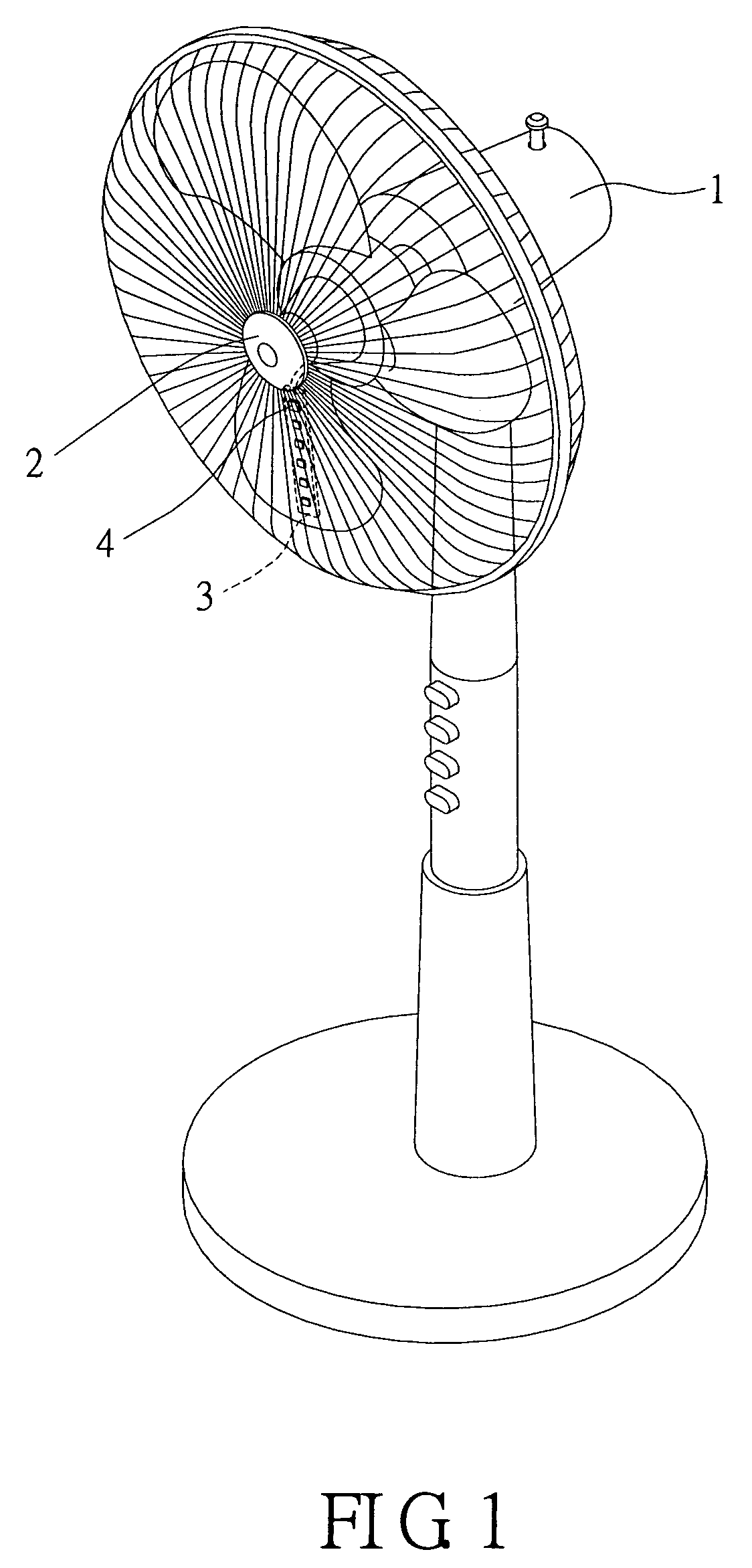
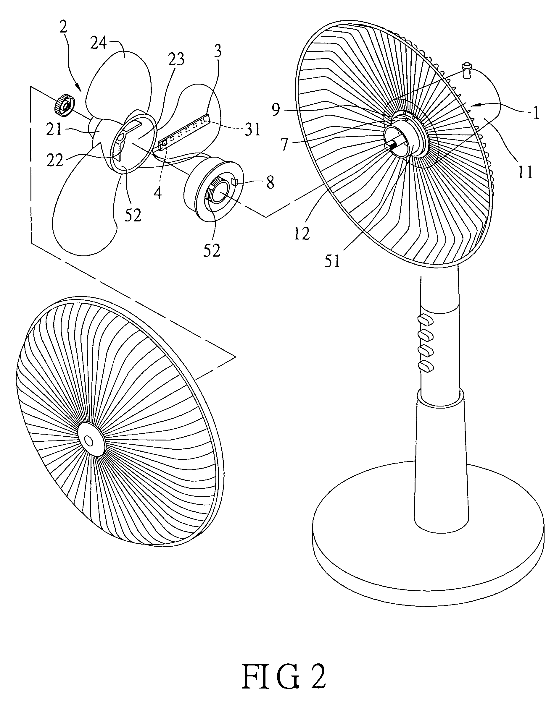
[0027]Reference is made to FIGS. 1 to 5. An automatic power generation light-image fan device of the present invention includes a fan motor 1, a vane set 2, a circuit board 3, a programmable chip 4, an automatic power generation component 5, a rectifier filter circuit 6, a connector 7, a magnetic sensor 8 and a positioning magnet 9. The fan motor 1 is formed by employing a base 11 with a shaft sleeve for sleeving on a mandrel 12 of silicon steel plates and a rotor and then combining through a bolt set. Because the actions between all these components are well-known in the prior arts, they will not be further discussed here.

[0028]The vane set 2 has an integrally formed housing base (rim) 21 mounted therein in an approximate circular form, and a central portion of the housing base 21 further has an axle hole 22 mounted thereon for passing there through the mandrel 12 of the fan motor 1. Moreover, an accommodating room 23 is formed on an inner surface of the housing base 21 passed thro...


PUM


Abstract

An automatic power-generation light-image fan device is described. It has a fan motor, a vane set, a circuit board, a programmable chip, an automatic power-generation component, a rectifier filter circuit, a magnetic sensor and a positioning magnet. In this device, the circuit board is mounted on the vanes of the vane set and also has plural light-emitting elements, which are respectively connected to I / O terminals of the programmable chip, and an accommodating room is mounted on an inner surface of the vane set, in which an inner circular surface of the accommodating room is circularly mounted by an inductance coil whose ends are connected to an input terminal of the rectifier filter circuit. Thereby, the light-emitting elements mounted on the fan can be controlled to generate various different twinkling light-image variations and an effect of persistence of vision when the fan motor is rotating.

Description

[0001]This application is a Continuation-in-Part of application Ser. No. 10 / 994,352, filed on 23 Nov. 2004, now abandoded and entitled AUTOMATIC POWER GENERATION LIGHT-IMAGE FAN DEVICE.BACKGROUND OF THE INVENTION[0002]1. Field of the Invention[0003]The present invention is related to an automatic power generation light-image fan device, and more particularly to a fan device that can control light-emitting elements of the vanes to produce various twinkling light-images, also having an effect of persistence of vision and different light-mixing colors when the fan device is rotating.[0004]2. Description of Related Art[0005]Generally, a common fan does not have a light-emitting decoration or a warning function, and a fan with a light-emitting function is always a heat-dispersing fan, such as, for example, TW patent No. 520149. In this disclosure, several plugging holes are formed in a circular portion of a fan base in an isogonal manner, and light-emitting diodes are correspondingly loc...

Claims


Application Information

Patent Timeline
Patent Type & Authority Patents(United States)
IPC IPC(8): F02B63/04F03G7/08G09G3/14
CPCH02K7/1807Y10S362/812H02K21/28
Inventor FANG, YI FENG
Owner FANG YI FENG
Learn More