Power monitoring system that determines phase using a superimposed signal

a technology of power monitoring and superimposed signals, applied in the direction of power measurement by digital technique, phase sequence/synchronization indication, dynamo-electric motor meters, etc., can solve problems such as circuit breakers to trip

Active Publication Date: 2007-01-09
VERIS INDS
View PDF3 Cites 29 Cited by
  • Summary
  • Abstract
  • Description
  • Claims
  • Application Information

AI Technical Summary

Problems solved by technology

In this manner, if a load shorts and thereafter draws excessive current then the circuit breaker will trip.

Method used


Image

  • Power monitoring system that determines phase using a superimposed signal
  • Power monitoring system that determines phase using a superimposed signal
  • Power monitoring system that determines phase using a superimposed signal

Examples


Embodiment Construction

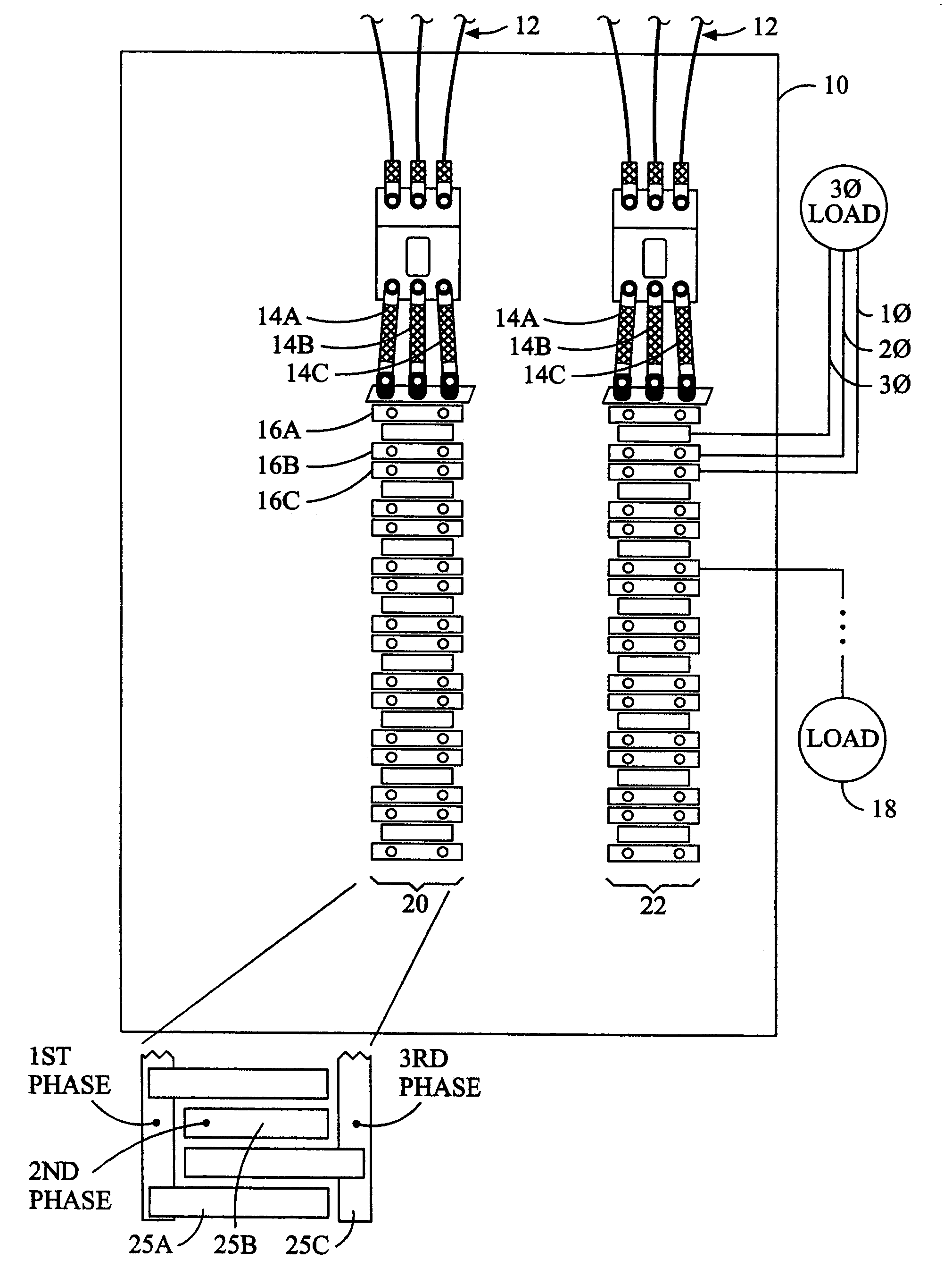
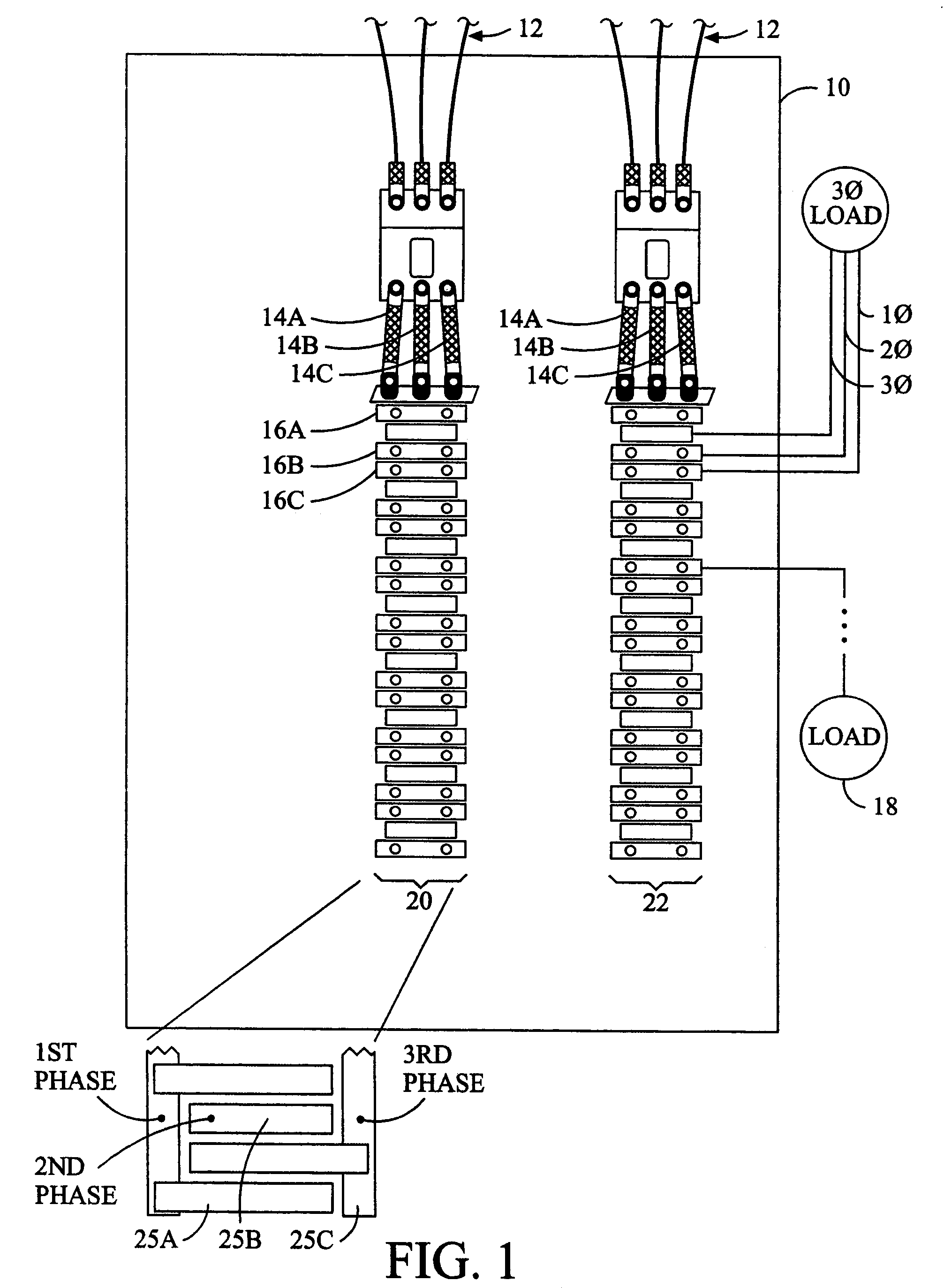
[0017]A power panel 10 provides a centralized location where the currents in the wires to several different loads may be sensed and the voltage in the bus bars that correspond with the currents may be sensed, with both being readily available. Moreover, the power provided from the bus bars to multiple different loads has the same voltage potential and phase relationship with respect to each of the different loads. In other words the power factor, which is a phase relationship between the voltage and current provided to a load, may be determined based on the current to the particular load and the voltage in the respective bus bar. For a plurality of different loads the relationship between the respective currents / voltages and power factor may be determined using the same bus bars. This commonality of voltages among different loads may be used by sensing the voltage potential together with its phase from each of the bus bars, preferably using one and only one electrical interconnectio...


PUM


Abstract

A power monitoring system comprising a first current sensor suitable to sense first changing electrical current within a first conductor to a first load and a first conductor. A second conductor sensing a first voltage potential provided to the first load. A power monitor superimposes a first signal on the first conductor and first current sensor such that the first signal is sensed on the other of the first conductor and first current sensor. Associating the first voltage potential with first changing electrical current in the power usage calculation of the first load.

Description

BACKGROUND OF THE INVENTION[0001]The present invention relates to a phase determination system.[0002]Referring to FIG. 1, many electrical power distribution systems include a panel enclosure 10 into which is provided electrical power using one or more sets of wires 12. The electrical power may have any voltage, any current, and any number of phases (e.g., single phase, two phases, or three phases). Each phase of the electrical power to the power panel is normally provided to a separate bus bar 14a, 14b, and 14c, which are normally elongate conductors within the power panel 10. A plurality of circuit breakers 16a, 16b, 16c, etc., which trip or otherwise selectively disconnect electrical power, are electrically interconnected between one or more of the bus bars 14a, 14b, and 14c, and respective loads 18 external to the power panel 10. In many power panels 10 the circuit breakers 16 are vertically aligned in one or more strips 20 and 22. When the load 18 interconnected to a respective ...

Claims


Application Information

Patent Timeline
Patent Type & Authority Patents(United States)
IPC IPC(8): G01R11/32
CPCG01R21/133G01R31/023G01R29/18G01R31/60
Inventor BRUNO, DAVID
Owner VERIS INDS
Why Eureka
Try Eureka