Method and arrangement for securing sensors in an electricity meter

a technology for electrical components and electricity meters, applied in transformers/inductance details, voltage/current isolation, instruments, etc., can solve the problems of labor and cost associated with assembling electricity meters, limiting factors in the cost of electricity meters, and complex bolt terminals or solder connections, etc., to achieve the effect of eliminating or eliminating

Active Publication Date: 2007-01-09
LANDIS GYR LLC
View PDF18 Cites 36 Cited by
  • Summary
  • Abstract
  • Description
  • Claims
  • Application Information

AI Technical Summary

Benefits of technology

[0013]The above needs are met by one or more of the inventive aspects described herein. One embodiment of the invention employs a mechanically-assembled current transformer cover that eliminates or at least reduces the need for thermoplastics or adhesives in insulating the current transformer. Another embodiment employs an arrangement that includes a post or protrusion di

Problems solved by technology

Because of the variety of components within meters, labor and cost associated with assembling electricity meters can be a limiting factor in cost of electricity meters.
All of the various interconnections, for example, between the blade and the current coil, require complex bolt terminals or solder connections, which are labor intensive.
Another source of cost arises from the need to isolate the current transformers in electricity meters.
It has been found, however, that the

Method used


Image

  • Method and arrangement for securing sensors in an electricity meter
  • Method and arrangement for securing sensors in an electricity meter
  • Method and arrangement for securing sensors in an electricity meter

Examples


Embodiment Construction

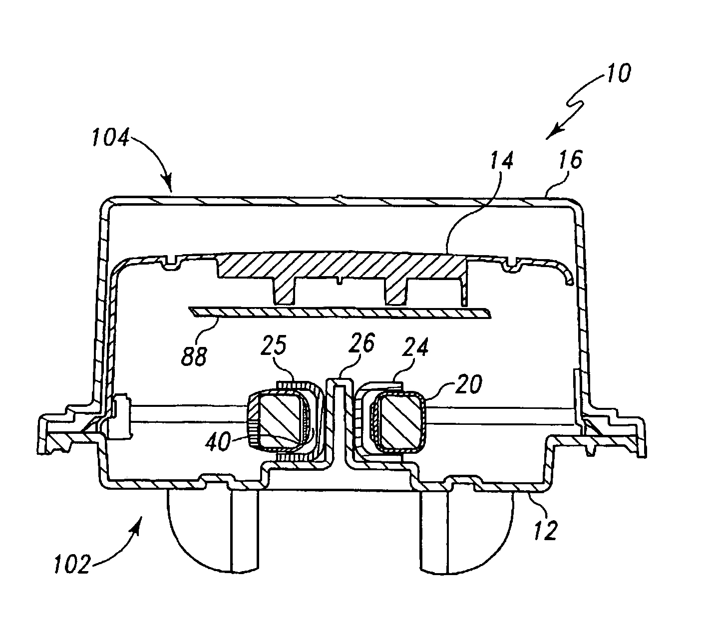
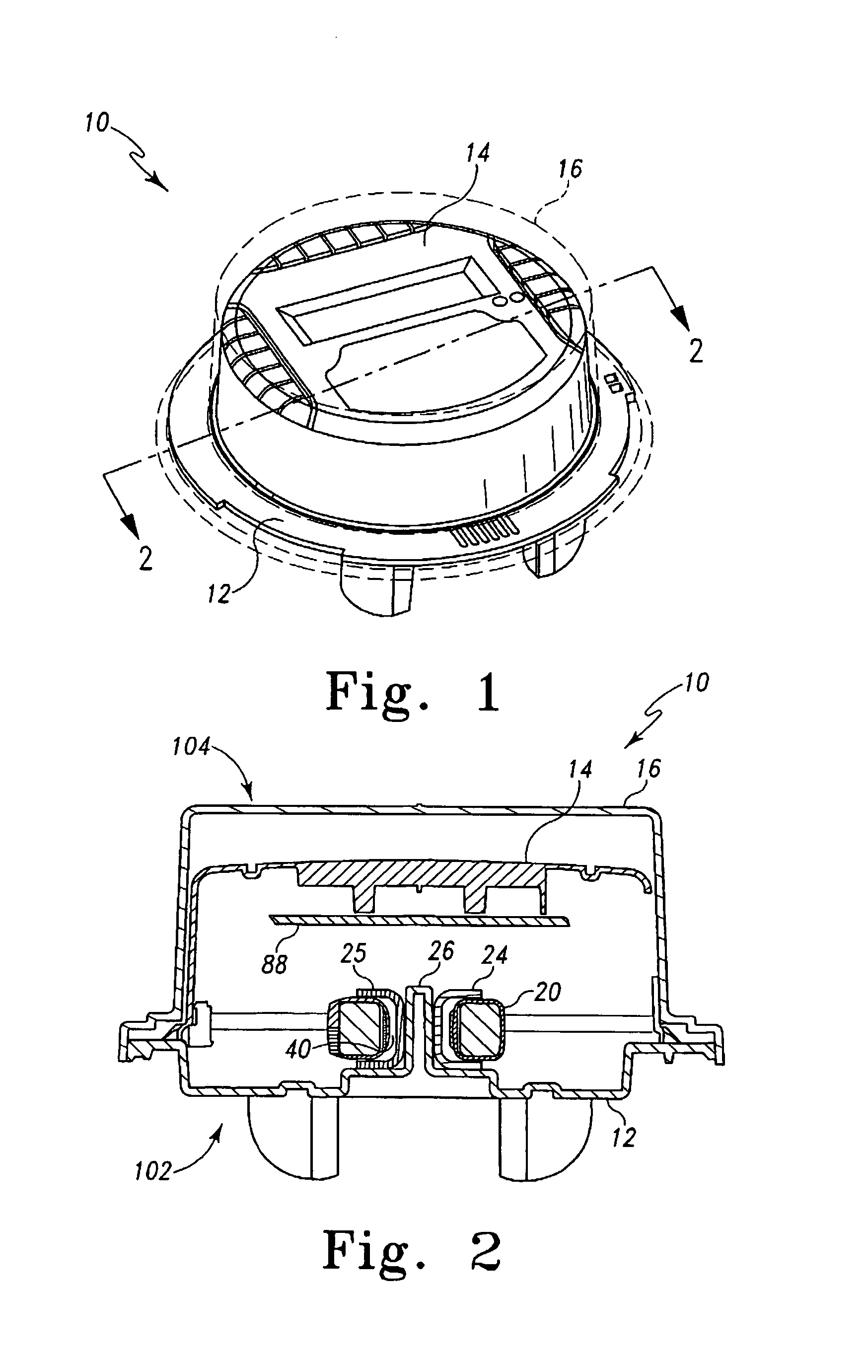
[0034]Referring now to FIGS. 1 and 2, there is shown an exemplary embodiment of an electric utility meter 10 which incorporates the features of the present invention therein. The electric utility meter 10 in the embodiment described herein is a residential meter having an electronic measurement circuit and an electronic display. However, it will be appreciated that many of the inventive aspects described herein may readily be adapted for use in polyphase meters used for non-residential purposes.

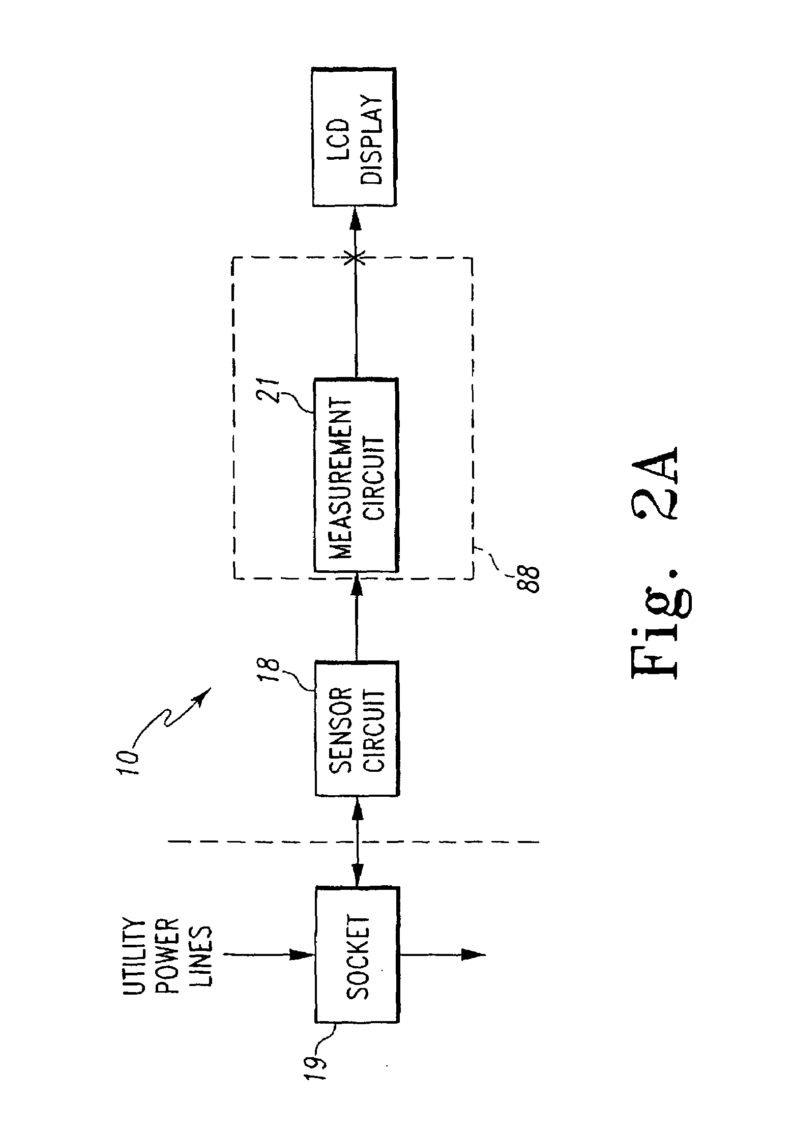
[0035]In general, the electric utility meter 10 has a housing that comprises a lower housing 12, an upper housing 14 and a cover 16. The lower housing 12 supports a sensor circuit 18 that attaches to a standard meter socket, not shown (see socket 19 of FIG. 2a). The upper housing 14 supports a circuit board 88 and a liquid crystal display (“LCD”) 74 (see FIGS. 9 and 10). The circuit aspects of the meter 10 are shown schematically in FIG. 2a.

[0036]The sensor circuit 18 is a circuit operable t...


PUM


Abstract

A current transformer assembly includes a current transformer and an insulation cup. The current transformer has a core and a first coil in a flux inducing relationship with the core. The core includes an opening defining a void configured to receive at least a second coil. The insulation cup includes a first part and a second part, the first part configured to mechanically couple to the second part such that the first part and the second part substantially encapsulate the current transformer. An interior portion of the insulation cup is disposed between the core and void.

Description

[0001]This application claims the benefit of U.S. Provisional Patent Application Ser. No. 60 / 447,607 filed Feb. 3, 2003, which is incorporated herein by reference.CROSS REFERENCE TO RELATE APPLICATIONS[0002]Cross-reference is made to co-pending U.S. Patent Application Express Mail No. EV389959001US, filed Feb. 3, 2004, entitled “Method and Arrangement for Connecting Electrical Components in an Electricity Meter”, and co-pending U.S. Patent Application Express Mail No. EV389959015US, filed Feb. 3, 2004, entitled “Utility Meter Housing Arrangement”.FIELD OF THE INVENTION[0003]The present invention relates generally to arrangements for securing electrical components, and more particularly, to arrangements for securing electrical components within an electricity meter.BACKGROUND OF THE INVENTION[0004]Electricity meters, or simply meters, are devices, that among other things, measure electrical energy consumed by a residence, factory, commercial establishment or other such facility. Elec...

Claims


Application Information

Patent Timeline
IPC IPC(8): H01F27/02G01R15/18G01R19/00
CPCG01R15/183G01R22/06G01R22/065
Inventor TATE, RONALD C.MEYERS, PAUL
Owner LANDIS GYR LLC
Why Eureka
Try Eureka