Data input device for tracking and detecting lift-off from a tracking surface by a reflected laser speckle pattern

a data input device and laser speckle technology, applied in the direction of input/output for user-computer interaction, instruments, computing, etc., can solve the problems of inconvenient and accurate cursor tracking, devices that lack the ability to track on any surface, devices that still require one moving part,

Active Publication Date: 2007-01-09
MICROSOFT TECH LICENSING LLC
View PDF40 Cites 46 Cited by
  • Summary
  • Abstract
  • Description
  • Claims
  • Application Information

AI Technical Summary

Problems solved by technology

Because such devices have a moving ball that must pass through a hole in the housing, such devices often become contaminated with dust and dirt, which may yield inaccurate or intermittent cursor tracking.
Thus, a major limitation of such a device is that it requires a tracking surface with particular characteristics, such as adequate friction and cleanliness, which are not readily found on all surfaces.
However, such devices lack the ability to track on any surface, requiring a suitable frictional interface between the ball and the surface.
Moreover, these devices still require one moving part, the ball.
In addition, aliasing artifacts may cause the cursor to skip, rather than move fluidly.
Although such devices are able to eliminate the moving ball, they are less universal by requiring a specific tracking surface to operate.
However, smooth surfaces with little color variation, such as surfaces with a fine microfinish similar to glass or clear plastic, may prove difficult to track upon.
Smooth surfaces generate no shadows from texture and present a low contrast image that may not provide adequate features upon which to track.
Surfaces with very little color variation also present a low contrast image that may not provide adequate features upon which to track.
However, these systems lack the ability to both track movement of a tracking surface over substantially any surface and detect when the device has been removed from the tracking surface for freezing the cursor.

Method used


Image

  • Data input device for tracking and detecting lift-off from a tracking surface by a reflected laser speckle pattern
  • Data input device for tracking and detecting lift-off from a tracking surface by a reflected laser speckle pattern
  • Data input device for tracking and detecting lift-off from a tracking surface by a reflected laser speckle pattern

Examples


Embodiment Construction

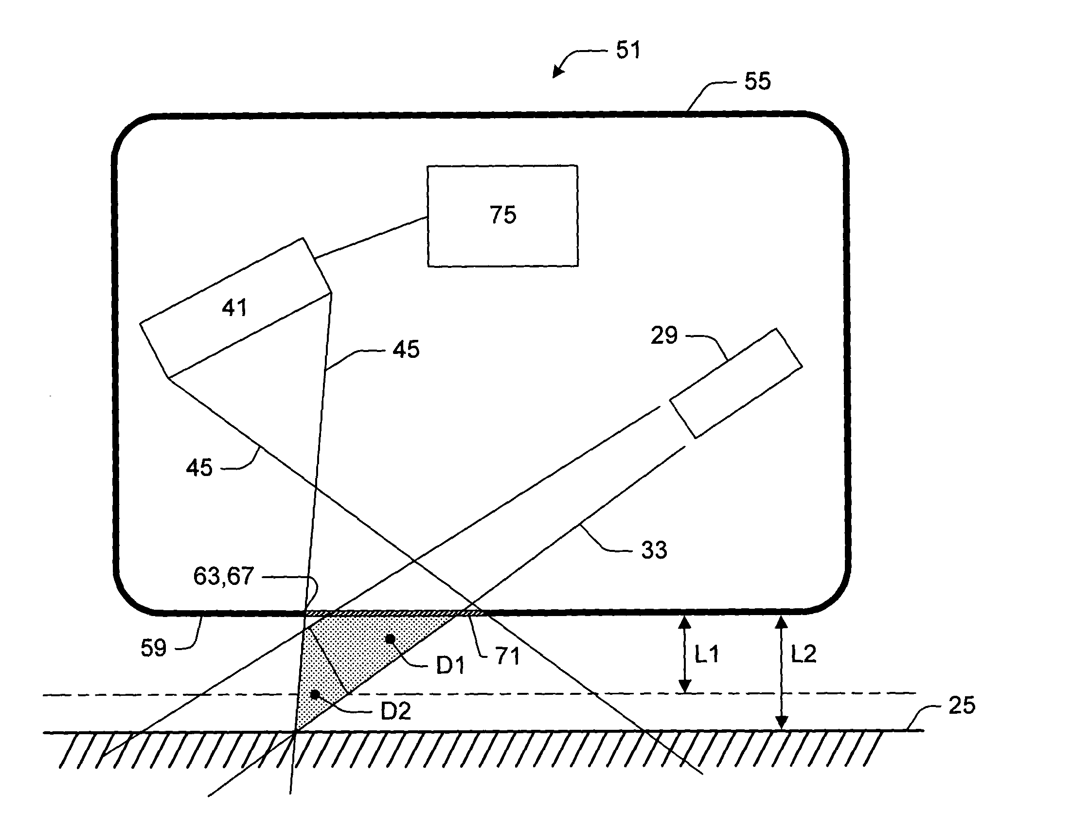
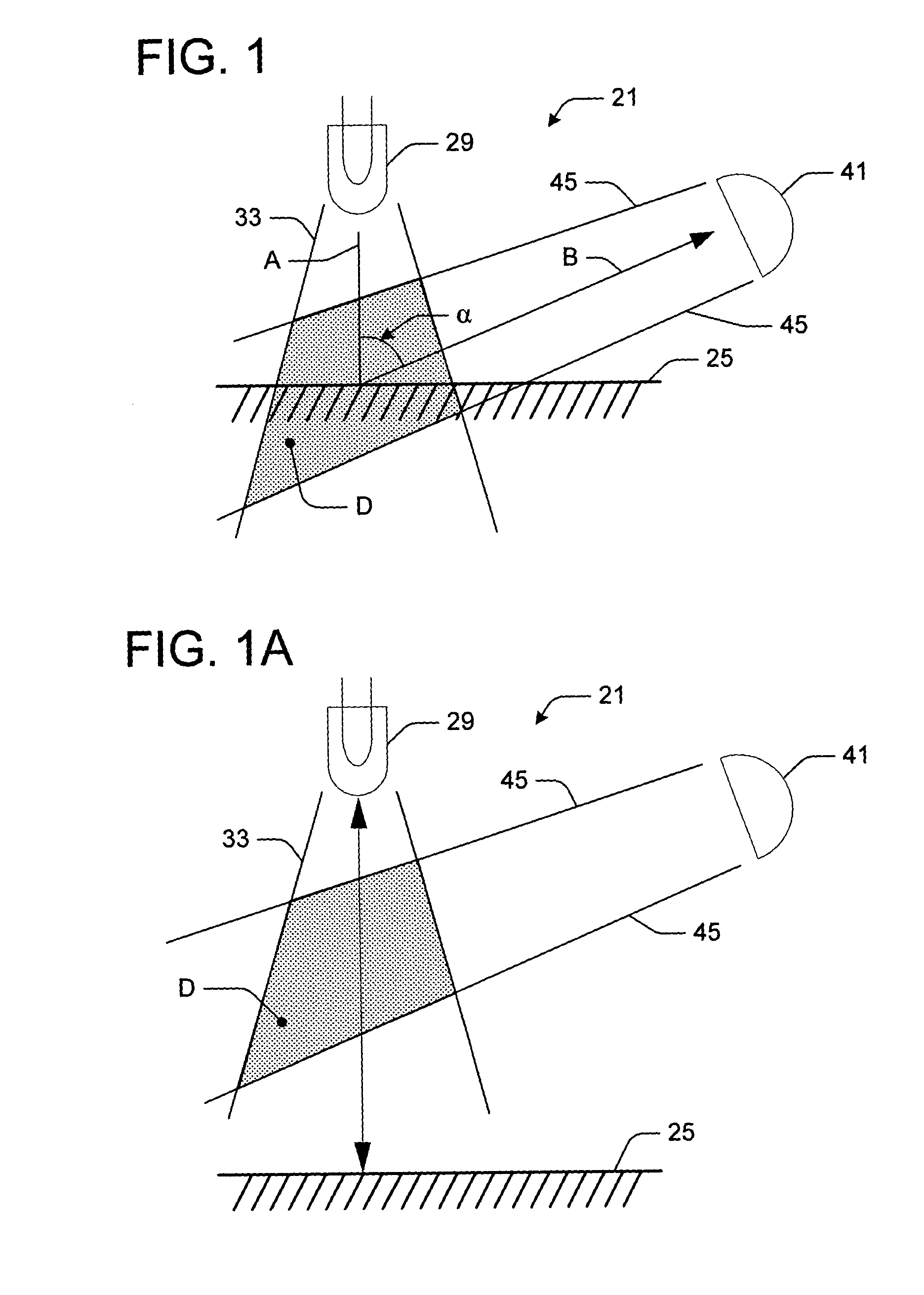
[0024]Referring first to FIGS. 1 and 1A, schematics of data input devices 21 for use with a tracking surface 25 are depicted. FIG. 1 depicts the tracking surface 25 within a detection zone D (shaded), and FIG. A depicts the tracking surface outside the detection zone. The device 21 of FIGS. 1 and 1A is greatly simplified to demonstrate the basic concepts of the present invention. FIGS. 3–4 provide a more detailed construction.

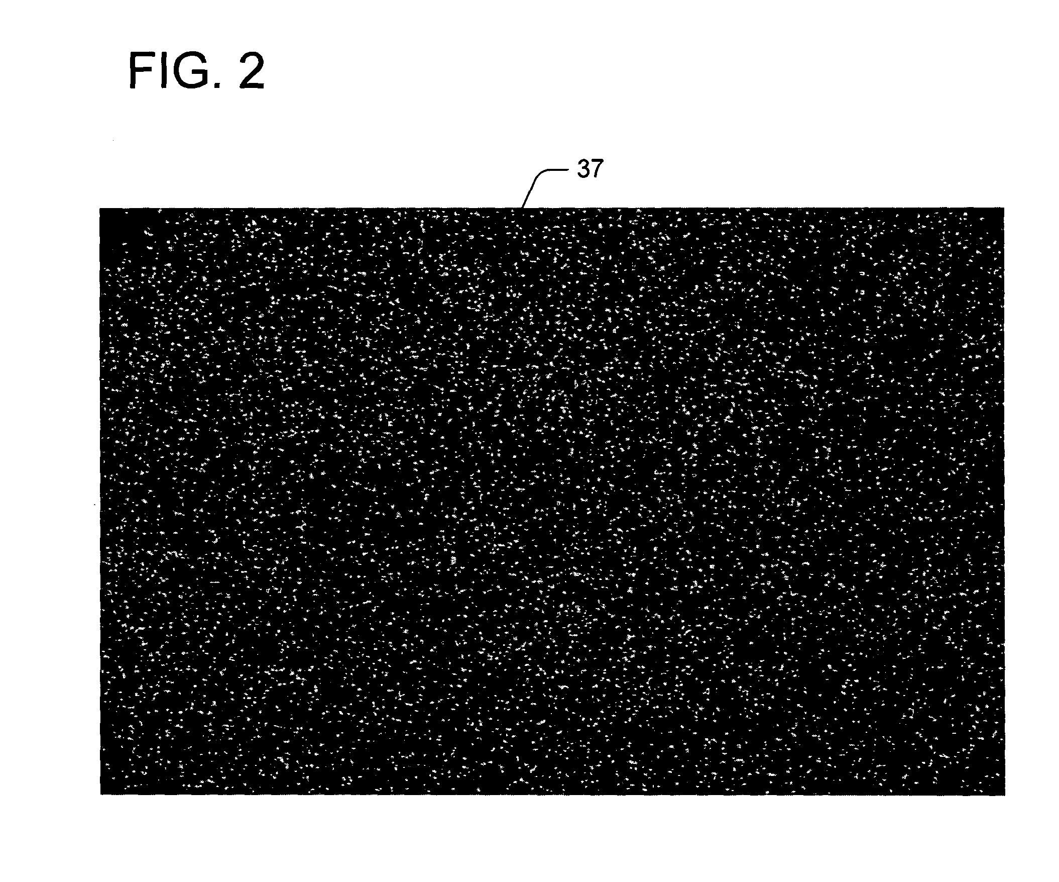
[0025]As shown in FIGS. 1 and 1A, a coherent light source 29 projects a coherent light beam 33, having a central axis A, onto the tracking surface 25. The tracking surface is a diffuse surface, having light-scattering properties sufficient to reflect a speckle pattern 37 (e.g., FIG. 2) when the coherent light beam 33 strikes the tracking surface. For example, paper, wood, metal, fabric, certain plastics and human skin each generally have sufficient surface variation to reflect a speckle pattern 37. Only surfaces that are perfectly reflective, i.e., mirrorlike, ...


PUM


Abstract

A data input device for use with a tracking surface having light-scattering properties. The device comprises a coherent light source for projecting a coherent light beam onto the tracking surface to reflect a speckle pattern. A detector having a field of view detects and images the speckle pattern. The detector operates in a tracking mode when the field of view intersects the coherent light beam. The intersection of the coherent light beam and the field of view comprise a detection zone. Relative movement between the coherent light beam and the tracking surface within the detection zone between is detected in the tracking mode, based on the reflected speckle pattern. Relative movement between the coherent light beam and the tracking surface outside the detection zone is not detected. A controller responsive to the detector operates in the tracking mode for correlating the imaged laser speckle pattern to track the relative movement within the detection zone.

Description

INCORPORATION BY REFERENCE[0001]The following U.S. patent is hereby fully incorporated by reference: U.S. Pat. No. 6,531,692 B1 issued to Adan et al., entitled “OPTICAL COUPLING ASSEMBLY FOR IMAGE SENSING OPERATOR INPUT DEVICE”, and assigned to Microsoft Corporation.TECHNICAL FIELD[0002]Embodiments of the present invention relate to the field of computer input devices, and particularly data input devices, such as a mouse or optical pen, employing coherent light striking a tracking surface. In particular, embodiments of this invention relate to data input devices defining and controlling a detection zone defined by the intersection of a coherent light beam and a field of view of a detector for detecting a speckle pattern and operating in a tracking mode when the tracking surface is within the detection zone and a non-tracking mode when the tracking surface is outside the detection zone.BACKGROUND OF THE INVENTION[0003]Previous computer input devices, such as mice, include rotatable b...

Claims


Application Information

Patent Timeline
Patent Type & Authority Patents(United States)
IPC IPC(8): G09G5/08G06F3/03G09G5/00
CPCG06F3/0317G06F3/0304G06F3/03543G06F3/038
Inventor BATHICHE, STEVEN NABILSTARKWEATHER, GARY KEITH
Owner MICROSOFT TECH LICENSING LLC
Why Eureka
Try Eureka