Use of buffer tube coupling coil to prevent fiber retraction

a technology of coupling coil and buffer tube, which is applied in the direction of optics, fibre mechanical structures, instruments, etc., can solve the problems of fiber retracting, cable tension, significant disruption of network function, etc., and achieves reduced cable diameter, reduced cable length, and reduced cable length

Active Publication Date: 2007-01-09
DRAKA COMTEQ BV
View PDF4 Cites 145 Cited by
  • Summary
  • Abstract
  • Description
  • Claims
  • Application Information

AI Technical Summary

Benefits of technology

[0012]The cable of the present invention preferably includes the first and second coupling coils located in the splice enclosures. Advantageously, the present invention provides a coupling coil with a significantly smaller diameter than prior methods. Further, the smaller coupling coil can be placed inside a closure to provide a more visually pleasing cable termination. Cable terminations according to the present invention also yield savings in time and effort, and further require less cable in their installation.

Problems solved by technology

When a cable is installed between termination points, the cable is subject to tension.
This lack of adequate coupling leads to the fiber retracting into the cable.
Fiber retraction can lead to significant disruptions in network function.
If the fibers can move freely, this can result in the fibers being pulled out of splice closures as they retract into the cable.
This causes problems with the splice closures and severely, if not detrimentally, affects optical performance of the fiber and cable.
However, each of these conventional methods has their own negative implications.
This results in frictional coupling of the internal fibers to the buffer tube to prevent the fiber from moving relative to the other members of the cable.
However, because the minimum bend radius of the cable is dictated by the external members of the cable, such as the jacket and strength members, conventional coupling coils can be quite large and bulky.
Such large coupling coils are undesirable since they are visually unpleasing in applications where cable is installed in residential areas, such as a fiber to the home installation.
Further, in many cases, it is not possible to make large coils on telephone poles or lines due to proximity to other cables and / or right of way restrictions.
Moreover, conventional coils require a significant length of cable to be utilized to form the large diameter coil, which results in increased installation expense.

Method used


Image

  • Use of buffer tube coupling coil to prevent fiber retraction
  • Use of buffer tube coupling coil to prevent fiber retraction
  • Use of buffer tube coupling coil to prevent fiber retraction

Examples


Embodiment Construction

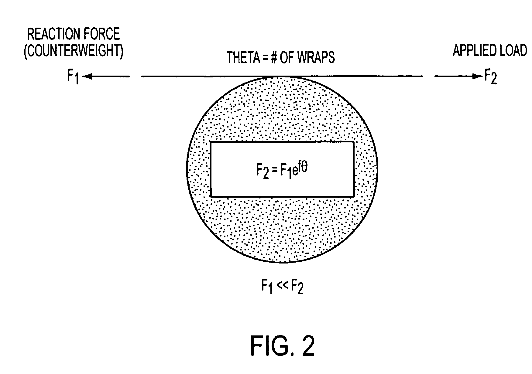
[0019]The present invention will now be described with reference to FIGS. 2–4. Fiber retraction can be prevented in cable installations by utilizing coupling coils, preferably located in terminations or splice closures. Coupling coils operate under the principal of utilizing sidewall friction of a coil, often times termed the capstan effect. The capstan effect is demonstrated in FIG. 2, where the reaction force F1 required to counteract the applied load F2 is exponentially related to friction factor (f) and number of wraps (θ). This relationship can be expressed as F2=F1eƒθ.

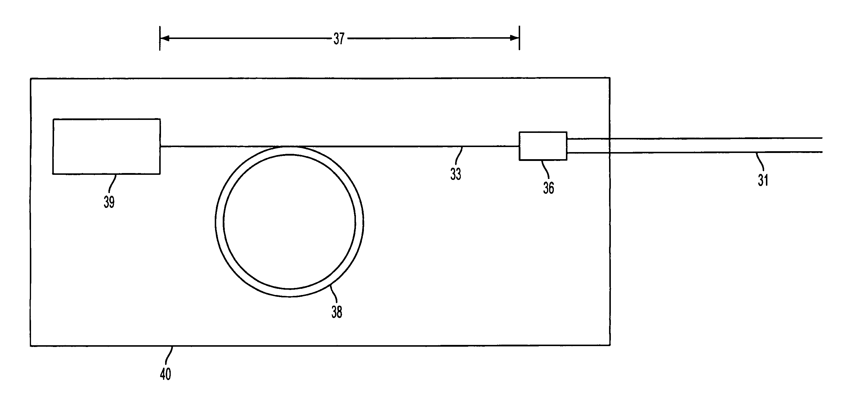
[0020]FIGS. 3A and 3B show a cable according to the present invention. The components of a fiber optic cable are described with respect to FIG. 3A. Fiber optic cable 31 includes at least one fiber 32 disposed in a buffer tube 33 and a jacket 34 surrounding the buffer tube. The cable may also include strength members 35 which assist in transferring the load on the cable 31 and may be used to secure the cable to a ...


PUM


Abstract

A method of installing a cable including at least one communication element, such as an optical fiber, disposed in a buffer tube and a surrounding jacket. The method includes the steps of exposing a portion of the buffer tube over a predetermined length and forming the exposed portion of the buffer tube into a coupling coil having at least one loop. The cable installation method prevents fiber retraction in cable terminations by utilizing at least one coupling coil formed from the exposed buffer tube and advantageously yields coupling coil terminations with small diameter coils, requiring less cable for more efficient installation, and further provides for the coupling coil to be located within a splice closure for more visually pleasing terminations. Preferably, coupling coils are formed at each end of the cable and located in splice enclosures.

Description

CROSS-REFERENCE TO RELATED APPLICATIONS[0001]The present application claims priority to U.S. provisional application No. 60 / 538,509, filed Jan. 26, 2004, the disclosure of which is hereby incorporated by reference thereto in its entirety, and the priority of which is claimed under 35 U.S.C. § 119(e).BACKGROUND OF THE INVENTION[0002]The present invention relates to the termination of fiber optic cable by a buffer tube coupling coil to couple the fiber with the buffer tube, thereby preventing fiber retraction.[0003]Fiber retraction refers to the movement of fibers into a cable when the cable is subjected to a tensile load. Fiber retraction occurs when fibers are not properly coupled to the cable. As the cable stretches longitudinally, the fibers want to remain in their un-strained state, and if they are not sufficiently coupled to the cable, the ends of the fibers retract into the cable.[0004]Fiber retraction most commonly occurs in central tube fiber optic cable. A central tube cable...

Claims


Application Information

Patent Timeline
Patent Type & Authority Patents(United States)
IPC IPC(8): G02B6/44G02B6/48
CPCG02B6/483G02B6/4457
Inventor LOVIE, RAYSTORAASLI, OLAF
Owner DRAKA COMTEQ BV
Why Eureka
Try Eureka