
Integrated vehicle motion control system

a technology of motion control system and vehicle, which is applied in the direction of external condition input parameters, gas pressure propulsion mounting, driver input parameters, etc., can solve the problems of conflict between the control of the different motion control devices, difficult to ideally solve the above problem, and the different kinds of motion control devices described above require a lot of effort and a long period of time to achieve correlation and coordination among the motion control devices. achieve the effect of improving the accuracy of individual controlled variables and improving accuracy

Inactive Publication Date: 2007-01-09
TOYOTA JIDOSHA KK
View PDF30 Cites 66 Cited by
  • Summary
  • Abstract
  • Description
  • Claims
  • Application Information

AI Technical Summary

Benefits of technology

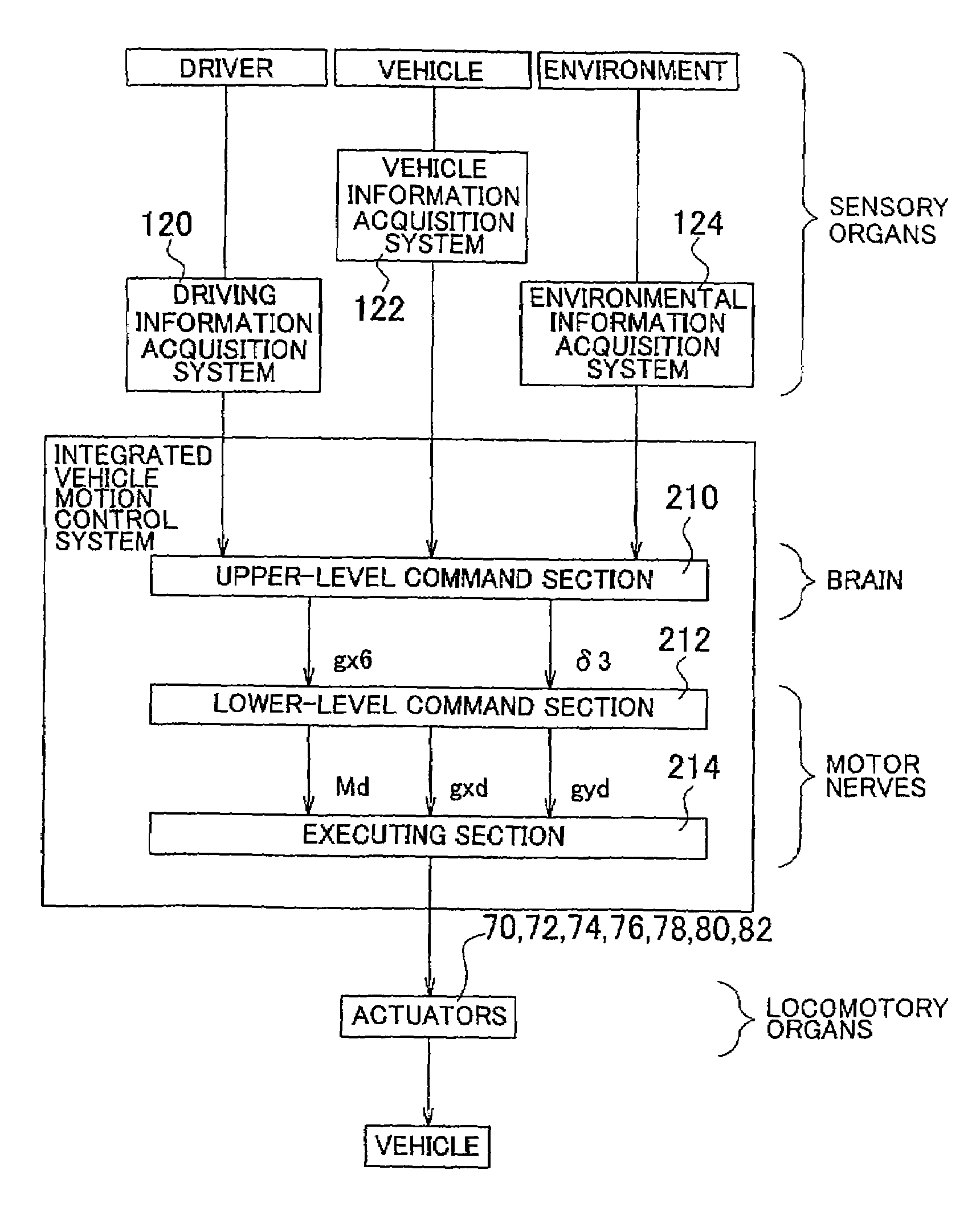
The invention is an integrated vehicle motion control system that uses a computer to control multiple actuators in a vehicle. The system is designed in a way that allows for easy development, design, and debugging of the software configuration. The system includes a command section that determines the target vehicle state quantity based on the driver's actions, an executing section that receives the command from the command section and executes it by controlling the actuators, and a software configuration that separates the command section and the executing section. This separation of the sections allows for independent development and design of each section, reducing the time required for the overall software configuration. The command section includes an upper-level command section and a lower-level command section, with the lower-level command section being responsible for accurately determining the target vehicle state quantity based on the dynamic behavior of the vehicle. The system also includes an upper-level command section and a lower-level command section that are not in a subordinate relationship, allowing for independent development and design of each section.

Problems solved by technology

However, the effects achieved by the motion control devices of different kinds do not necessarily appear in the vehicle independently of each other, but may interfere with one another.
However, the development of the vehicle with the different kinds of the motion control devices as described above requires a lot of efforts and a long period of time for achieving correlation and coordination among the motion control devices.
With this arrangement, if the motion control devices need to operate the same actuator(s) at the same time, a problem of conflict arises between controls by the different motion control devices.
It is difficult to ideally solve the above problem if the correlation / coordination of the motion control devices is established in a supplemental or additional way after the individual motion control devices were developed independently of each other, as described above.
In the known example, while the above-described system is constructed in the hierarchical form in accordance with the relationship of components on the hardware configuration, the software configuration adapted for carrying out the plurality of kinds of motion controls does not necessarily have an appropriate hierarchical arrangement.
However, the above U.S. Patent does not mention a technology for adequately arranging the software configuration of the system in hierarchical form.

Method used


Image

  • Integrated vehicle motion control system
  • Integrated vehicle motion control system
  • Integrated vehicle motion control system

Examples


Embodiment Construction

[0169]An exemplary embodiment of the invention will be described in detail with reference to the accompanying drawings.

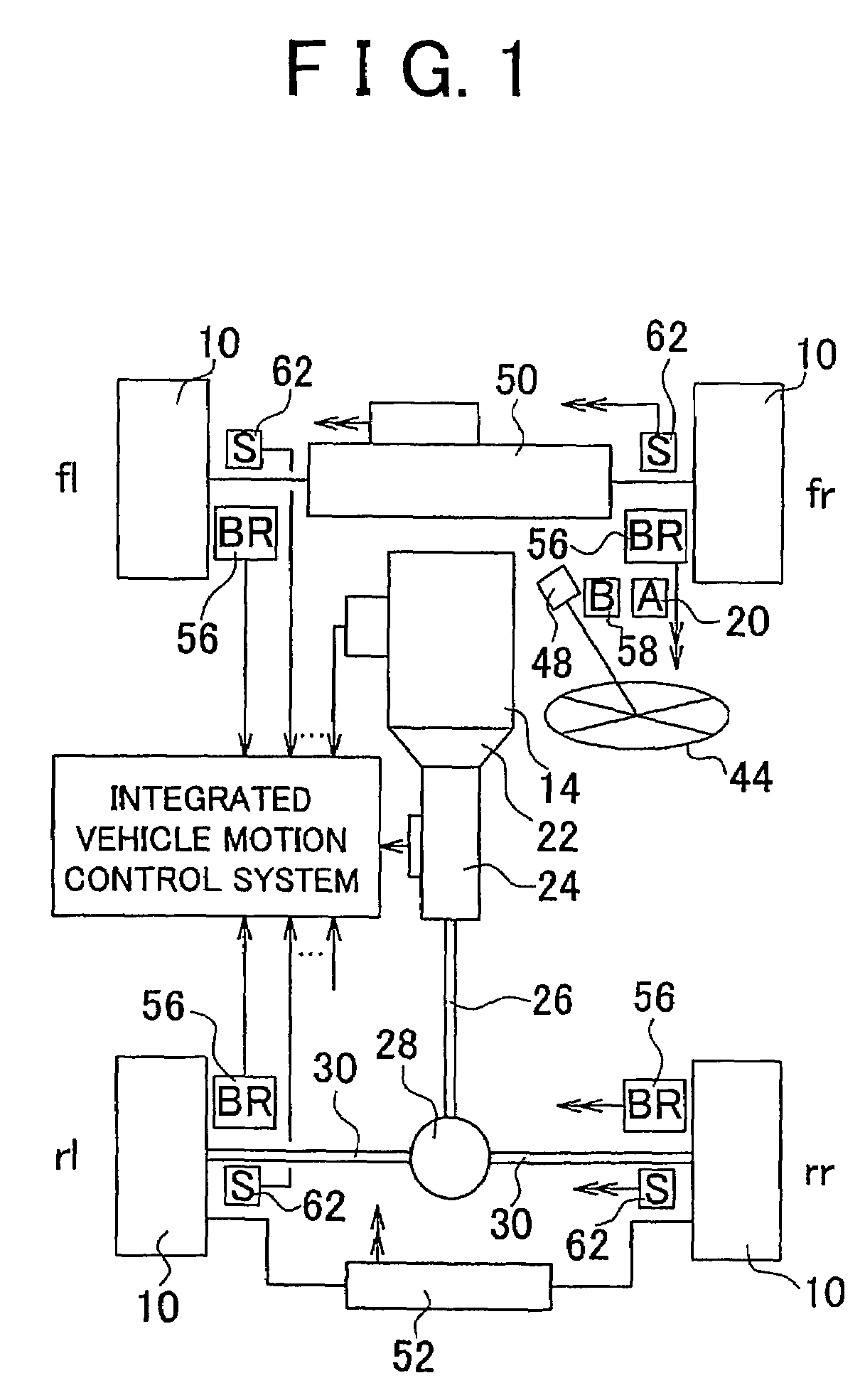
[0170]FIG. 1 is a plan view schematically showing a motor vehicle on which an integrated vehicle motion control system according to one exemplary embodiment of the invention is installed. The integrated vehicle motion control system will be hereinafter simply referred to as “motion control system”.

[0171]The vehicle of FIG. 1 includes front-left, front-fight, rear-left and rear-fight wheels 10. In FIG. 1, “fl” denotes a front-left wheel, “fr” denotes a front-fight wheel, “rl” denotes a rear-left wheel, and “rr” denotes a rear-fight wheel. The vehicle also includes an engine (internal combustion engine) 14 as a driving power source. The operating state of the engine 14 is electrically controlled depending upon an amount or degree by which an accelerator pedal 20 (as one example of an acceleration operating member) is operated by a driver of the vehicle. The operating ...


PUM


Abstract

An integrated vehicle motion control system is provided in which the software configuration is formed in a hierarchical structure, and includes (a) a command section adapted to determine target vehicle state quantities based on driving related information, and (b) an executing section adapted to receive the target vehicle state quantities as commands from the command section, and execute the commands by means of a plurality of actuators. The command section includes an upper-level command section adapted to determine first target vehicle state quantities based on the driving related information, without taking account of the dynamic behavior of the vehicle, and a lower-level command section adapted to determine second target vehicle state quantities inview of the dynamic behavior of the vehicle.

Description

BACKGROUND OF THE INVENTION[0001]1. Field of the Invention[0002]The invention relates to a technology for controlling a plurality of actuators in an integrated manner so as to perform a plurality of kinds of vehicle motion controls on a motor vehicle.[0003]2. Description of Related Art[0004]In recent years, there is an increasing tendency to install many kinds of motion control devices for controlling movements of the vehicle on the same vehicle. However, the effects achieved by the motion control devices of different kinds do not necessarily appear in the vehicle independently of each other, but may interfere with one another. When the development of the vehicle involves installation of the plural kinds of motion control devices on the vehicle, therefore, it is important to ensure sufficient cooperation (or coaction) and coordination of these motion control devices.[0005]For example, when a plurality of kinds of motion control devices need to be mounted in the same vehicle at a cer...

Claims


Application Information

Patent Timeline
Patent Type & Authority Patents(United States)
IPC IPC(8): B60R16/02G06F17/00B60G17/015B60K6/20B60K6/54B60R21/00B60T8/00B60T8/17B60T8/172B60T8/1755B60T8/58B60W10/00B60W10/04B60W10/06B60W10/08B60W10/10B60W10/103B60W10/18B60W10/184B60W10/20B60W10/22B60W20/00B60W30/00B60W40/10B60W40/105B60W40/109B60W50/00B62D6/00B62D101/00B62D111/00B62D113/00B62D119/00B62D127/00B62D133/00B62D137/00F02D29/02F02D41/00F02D41/26F16H61/46G06F15/76H04L29/06H04L29/08
CPCB60W50/00F02D41/26H04L29/06H04L67/12B60K2741/006B60K2741/283B60W2050/0004B60W2540/10H04L69/329B60W2550/12B60W2540/12B60W30/1819B60W2555/20B60W2050/0006B60W50/06B60W50/08H04L9/40
Inventor KOIBUCHI, KENMIYAGO, SHOUICHI
Owner TOYOTA JIDOSHA KK
Learn More