Remote power control system

a remote control and power control technology, applied in computer control, data switching networks, instruments, etc., can solve the problems of not being particularly efficient, complicated to implement snmp, and high cost of dispatching third-party maintenance technicians, so as to reduce the time it takes to restore a failed network appliance, improve service level measures, and recapture the cost of implementing the present invention

Inactive Publication Date: 2007-01-09
SERVER TECHNOLOGY
View PDF13 Cites 59 Cited by
  • Summary
  • Abstract
  • Description
  • Claims
  • Application Information

AI Technical Summary

Benefits of technology

[0022]Briefly, an SNMP network embodiment of the present invention comprises a power manager with an SNMP agent in TCP / IP communication over a network with an SNMP network manager. The power manager is connected to control several intelligent power modules each able to independently control the power on / off status of several network appliances in an equipment rack at a common remote node, e.g., a point-of-presence site. Power-on and load sensors within each intelligent power module are able to report the power status of each network appliance to the SNMP network manager with MIB variables in response to GET commands. Each intelligent power module is equipped with an output that is connected to cause an interrupt signal to the network appliance being controlled. The SNMP network manager is able to test which network appliance is actually responding before any cycling of the power to the corresponding appliance is tried.
[0023]An advantage of the present invention is that a system and method are provided that can help an operator avoid the mistake of turning on or off the wrong network appliance in a busy equipment rack at a remote site.
[0025]A further advantage of the present invention is that a system and method are provided that allows a network console operator to investigate the functionality of the electrical power status when a router or other network device has been detected as failing.
[0026]A still further advantage of the present invention is that a system and method are provided for reducing the need for enterprise network operators to dispatch third party maintenance vendors to remote equipment rooms and POP locations simply to power-cycle failed network appliances. The costs to dispatch such third party maintenance vendor can run from $300–$600 per call. The cost of implementing the present invention can be recaptured in less than one year, e.g., by reducing the number of third party maintenance dispatches to remote locations.
[0027]Another advantage of the present invention is that a system and method are provided for reducing the time it takes to restore a failed network appliance and improving service level measures.
[0028]Another advantage of the present invention is that a system and method are provided for reducing organization losses from network downtime. Being able to immediately power-cycle a failed server and thus return the server to operation can directly reduce the downtime loss to the organization.

Problems solved by technology

Many network appliances are typically connected to a single UPS, and this sets up a problem.
Organizational down-sizing has been used throughout the corporate world to reduce non-network costs, and that usually translates to fewer technical people available in the right places to support large and complex in-house global networks.
The costs associated with dispatching third-party maintenance technicians is very high, and the dispatch and travel delay times can humble the business operations over a wide area for what seems an eternity.
Particular network application tool software is available to report lists of the network appliances, by location, and can issue trouble lists and keep track of software versions and releases.
Unfortunately, SNMP is a complicated protocol to implement, due to complex encoding rules, and it is not a particularly efficient protocol.
Bandwidth is often wasted with needless information, such as the SNMP version that is to be transmitted in every SNMP message, and multiple length and data descriptors scattered throughout each message.
Such identification leads to needlessly large data handles that can consume substantial parts of each SNMP message.
Conventional SNMP network management technologies do not provide sufficient information related to the nodes' electrical power status.
But the console operator would know only that the router is failing.
However, the console operator does not have any information about the electrical power status to the router, e.g., has the router power switch been moved to the OFF position or has the switch been accidentally turned OFF?
The electrical power source could have failed, the power cable connection become loose, or a technician may have accidentally removed the router from a rack.

Method used


Image

  • Remote power control system
  • Remote power control system
  • Remote power control system

Examples


Embodiment Construction

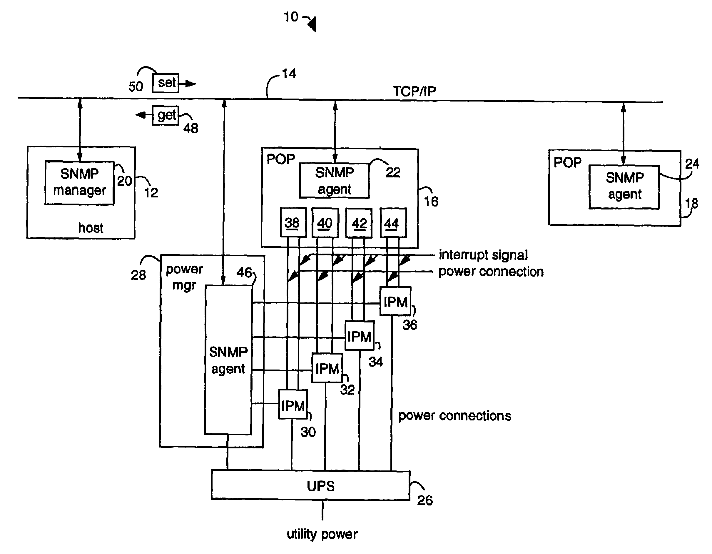
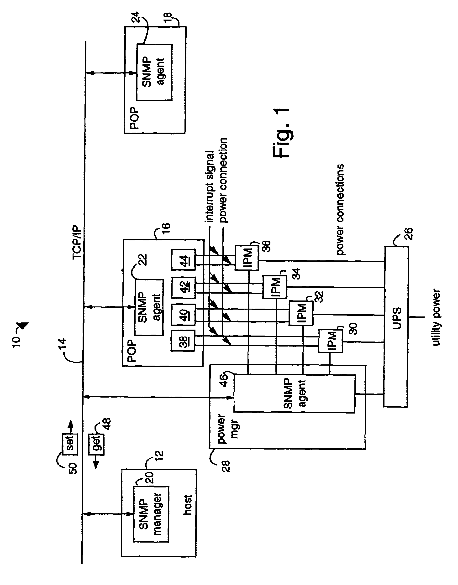
[0035]FIG. 1 illustrates a simple network management protocol (SNMP) network embodiment of the present invention, referred to herein by the general reference numeral 10. The SNMP network 10 includes a host 12 with a TCP / IP connection 14 to a plurality of point-of-presence (POP) nodes represented by a pair of network equipment racks 16 and 18. SNMP network management is provided by a SNMP manager 20 in communication with a respective pair of SNMP agents 22 and 24 at the remote nodes. The SNMP manager 20 may comprise a commercial product such as IBM NETVIEW / 6000, HP OPENVIEW, POLYCENTER, SunNet MANAGER, Cabletron SPECTRUM, etc.

[0036]An uninterruptable power supply (UPS) 26 provides operating power to a TCP / IP-addressable enterprise power manager 28. It also powers a plurality of intelligent power modules (IPM's) 30, 32, 34, 36 that are able to switch the operating power on / off to a corresponding network appliances 38, 40, 42, 44.

[0037]An SNMP agent 46 is private to the power manager 2...


PUM


Abstract

An SNMP network comprises a power manager with an SNMP agent in TCP / IP communication over a network with an SNMP network manager. The power manager is connected to control several intelligent power modules each able to independently control the power on / off status of several network appliances. Power-on and load sensors within each intelligent power module are able to report the power status of each network appliance to the SNMP network manager with MIB variables in response to GET commands. Each intelligent power module is equipped with an output that is connected to cause an interrupt signal to the network appliance being controlled. The SNMP network manager is able to test which network appliance is actually responding before any cycling of the power to the corresponding appliance is tried.

Description

CO-PENDING APPLICATIONS[0001]This is a Continuation application of U.S. patent application Ser. No. 10 / 758,117 filed Jan. 16, 2004 now U.S. Pat. No. 7,010,589 which is a Divisional of U.S. patent application Ser. No. 09 / 375,471 filed Aug. 16, 1999 now U.S. Pat. No. 6,711,613 which is a Continuation-In-Part of U.S. patent application Ser. No. 08 / 685,436 filed Jul. 23, 1996, now U.S. Pat. No. 5,949,974 the contents of which are hereby incorporated by reference in its entirety.BACKGROUND OF THE INVENTION[0002]1. Field of the Invention[0003]The invention relates generally to automatic power control and more particularly to remote control methods and devices to maintain computer network system availability.[0004]2. Description of the Prior Art[0005]Enterprise networks exist to support large world-wide organizations and depend on a combination of technologies, e.g., data communications, inter-networking equipment (frame relay controllers, asynchronous transfer mode (ATM) switches, routers...

Claims


Application Information

Patent Timeline
Patent Type & Authority Patents(United States)
IPC IPC(8): G06F15/173G06F1/26H02B1/00G06F1/32
CPCG06F1/26G05B15/02G06F1/3246H02J3/14H02J13/0062H04L12/2697H04L41/0213H04L43/0817H04L43/50G06F1/3209Y02B70/3225Y02B90/2638Y04S20/222Y04S40/124Y04S40/168G05F1/66H02J2310/12H02J13/00016H02J13/00004Y02B90/20Y04S40/00
Inventor EWING, CARREL W.CLEVELAND, ANDREW J.
Owner SERVER TECHNOLOGY
Why Eureka
Try Eureka