Electrical connector with coding function

Active Publication Date: 2017-12-07
APTIV TECH LTD
View PDF6 Cites 0 Cited by
  • Summary
  • Abstract
  • Description
  • Claims
  • Application Information

AI Technical Summary

Benefits of technology

[0005]The object of the invention is to provide an electrical connector which can be used in vehicles as connecting elements i

Problems solved by technology

It is extremely important to hold the sealing feature in position since with incorrect sealing, moisture in the connector can lead

Method used


Image

  • Electrical connector with coding function
  • Electrical connector with coding function
  • Electrical connector with coding function

Examples


Example

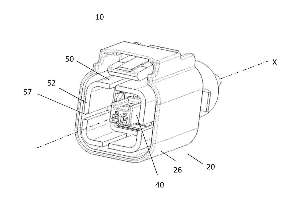
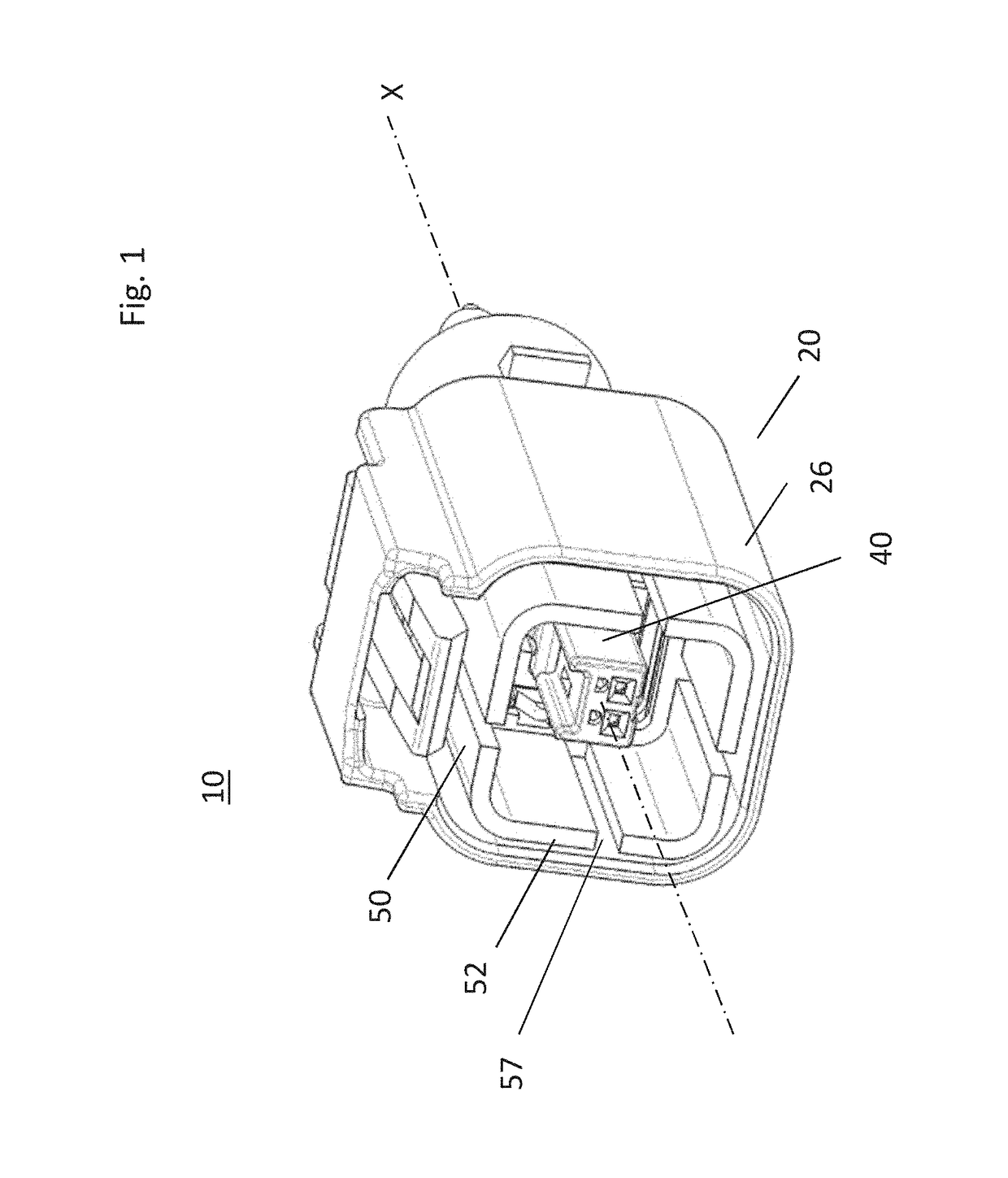
[0033]FIG. 1 shows a non-limiting example of a connector 10 in a perspective view. The illustration shows the area which is connected to the mating connector 110 during mating. The second collar 26 partially surrounds the coding element 50, which in turn partially surrounds the second connector housing 40. From the second end 52, slit-shaped recesses 57 extend rectilinearly along the connecting axis X into the material of the coding element 50. In this illustration, the coding element 50 has four recesses 57 distributed over its circumference. The second connector housing 40 is held centrally in the first connector housing 20. The second connector housing 40 is attached somewhat recessed in relation to the second end 52 of the coding element 50. This ensures that the coding element 50 first must find its guidance during connecting before the second connector housing 40 finds its counterpart. This structure protects the small second connector housing 40 from damage.

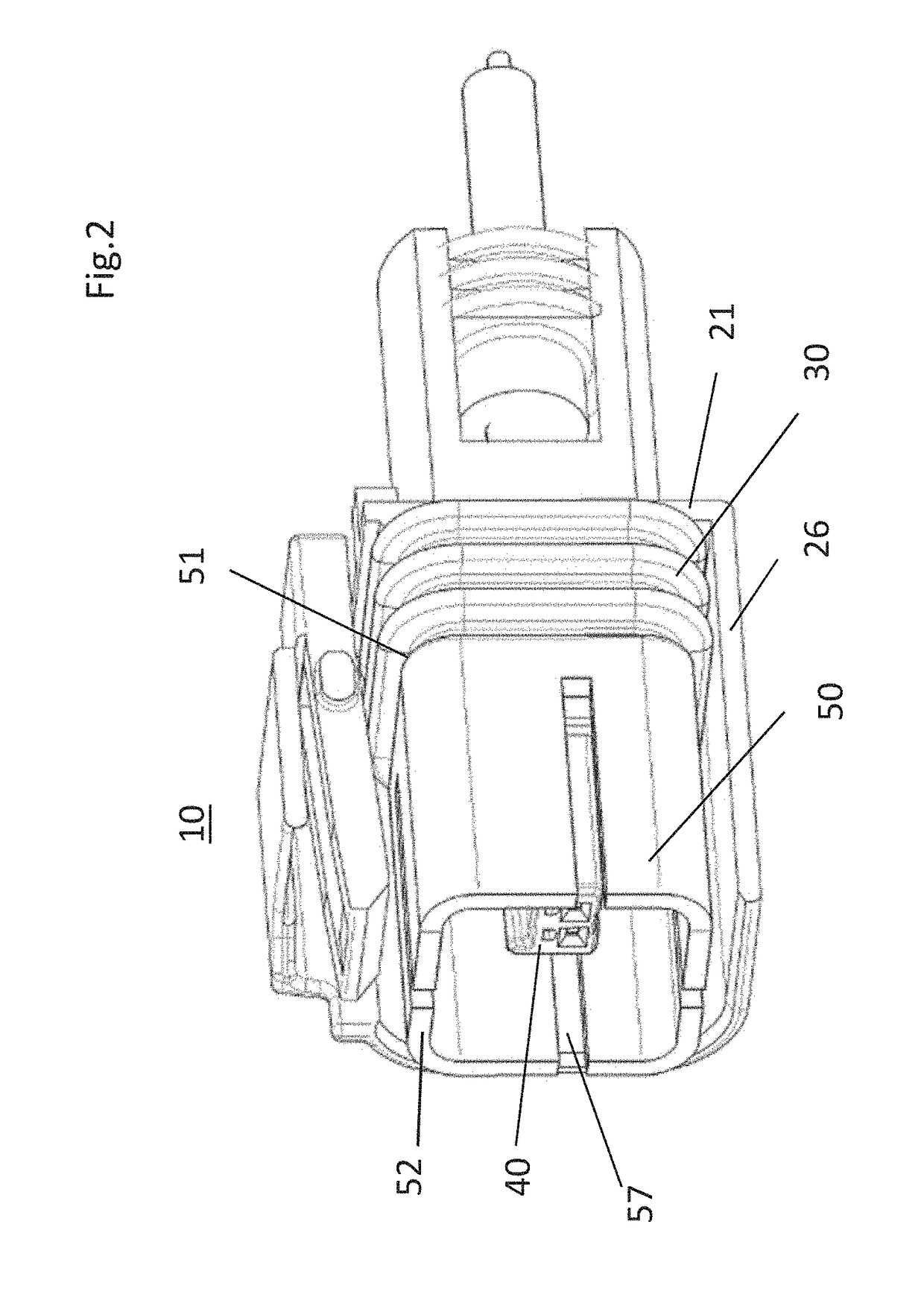
[0034]In FIG. 2, a...


PUM


Abstract

The present invention relates to an electrical connector including a first connector housing with a wall arranged substantially perpendicular to the connecting axis. The wall has an opening for insertion of a second connector housing. A first collar extends from the wall concentrically around the opening. A second collar extends from the wall concentrically around the first collar. The first collar and the second collar are spaced apart. A sleeve-shaped coding element is attached with a first end to the free end of the first collar. The first collar and the sleeve-shaped coding element are arranged concentrically around the opening. A sealing element is arranged in a sealing area between the first collar and the second collar. The sleeve-shaped coding element includes a supporting feature at its first end which is suitable for holding the sealing element in its position.

Description

CROSS-REFERENCE TO RELATED APPLICATION[0001]This application claims the benefit under 35 U.S.C. §119(a) of Patent Application No. 16172496.8 filed in the European Patent Office on Jun. 1, 2016, the entire disclosure of which is hereby incorporated by reference.TECHNICAL FIELD OF THE INVENTION[0002]The invention relates to a sealed electrical connector for use in high speed data transmission applications.BACKGROUND OF THE INVENTION[0003]With the further development of electronic driver assistance systems, the vehicles and associated technology are changing. The amount of data generated, for example, by a camera array can no longer be transmitted in real time via a conventional Controller Area Network (CAN) communication network with a transmission rate of approximately 500 kbps. One solution is the Ethernet standard, which is known from computer technology. It is viewed by vehicle manufacturers as a stable communication scheme for future vehicle networks. Since the climatic condition...

Claims


Application Information

Patent Timeline
IPC IPC(8): H01R13/641H01R13/646H01R13/52
CPCH01R13/641H01R13/5219H01R13/646H01R13/46H01R13/52H01R13/5216H01R13/506H01R13/645H01R13/5202H01R13/639H01R2201/26
Inventor LUDWIG, MARTINDROESBEKE, GERT
Owner APTIV TECH LTD
Why Eureka
Try Eureka