Storage system

a storage system and storage system technology, applied in memory systems, redundant hardware error correction, instruments, etc., can solve the problems of deteriorating the response time of cpu and throughput of storage systems, essentially unnecessary cost burden for cpu and storage systems, and similar problems of conventional remote copying techniques, so as to reduce extra load and time

Inactive Publication Date: 2007-01-09
HITACHI LTD
View PDF23 Cites 9 Cited by
  • Summary
  • Abstract
  • Description
  • Claims
  • Application Information

AI Technical Summary

Benefits of technology

[0034]In general, a storage device does not know the structure of a file system managed by a host and is therefore not capable of knowing which area does data forming a dataset or file exist in. In the present invention, there is provided means with which the host informs the storage device of the area. The storage device uses this means to generate a copy of only an area such as a dataset or file which is essentially required. Thereby, extra load and time are reduced.

Problems solved by technology

In the conventional technique of remote copying, since the unit of an object of copying is a logical volume, as mentioned above, the following problems are involved from the aspect of efficiency.
However, according to the conventional remote copying technique in which the copying is performed in units of a logical volume, unnecessary data is also copied, thereby causing overhead which is not necessary essentially.
Since a storage system of a primary site and a storage system of a secondary site are arranged with a long distance of several-ten kilometers to several-hundred kilometers from each other, the overhead caused by the copying of unnecessary data is large, thereby greatly deteriorating the response time for CPU and the throughput of the storage system.
Also, in the case where only a part of a logical volume of the primary site made an object subjected to copying is used, unused portions yielded in a logical volume formed at the secondary site in a manner paired with the logical volume made the object subjected to copying and with the same capacity as the logical volume made the object subjected to copying may be an essentially unnecessary burden of cost to the CPU and the storage system.
Also, such problems of the conventional remote copying technique are similarly encountered by the conventional migratory copying technique mentioned above.

Method used


Image

  • Storage system
  • Storage system
  • Storage system

Examples


first embodiment

I. First Embodiment

[0077]First, the description will be made of a first embodiment of the present invention.

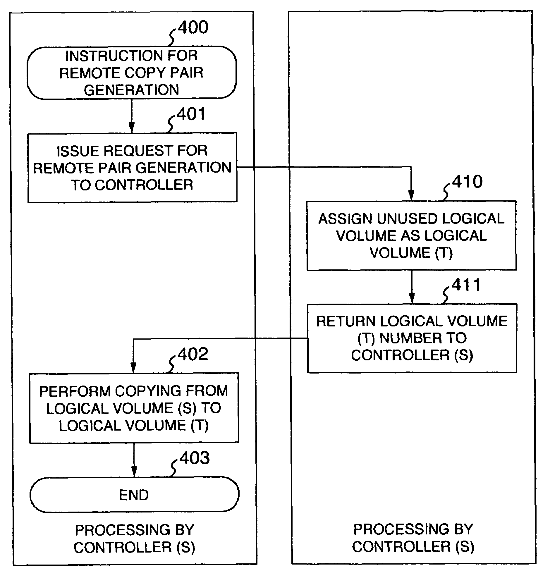
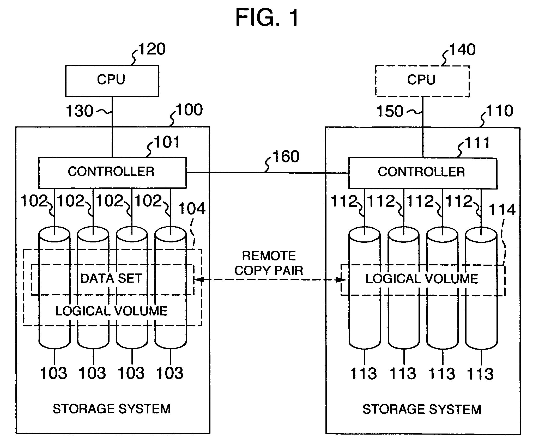
[0078]The first embodiment concerns remote copying. FIG. 1 shows an example of the construction of an information system in which the remote copying is performed.

[0079]One or more CPU's 120 and one or more storage systems 100 are arranged at a primary site where a main service is performed.

[0080]The CPU 120 executes an application program to issue a request for input / output of data of a logical volume 104 to the storage system 100 of the primary site. The logical volume 104 is logical storage devices which are recognized by the CPU 120.

[0081]The storage system 100 is connected to a storage system 110 of a secondary site through one or more inter-controller paths 160. The storage system 100 is composed of one or more controllers 101 and one or more storage devices 103. The controller 101 performs the transfer of data between the CPU 120 and the storage device 103. In the contro...

second embodiment

II. Second Embodiment

[0149]In the second embodiment, there is performed migratory copying in which data migrates between new and old storage systems.

[0150]The description will now be made assuming that the migratory copying from a storage system 1100 to a storage system 1000 is performed, as shown in FIG. 7. The storage system 1000 serving as a copy destination has a controller 1010 and storage devices 1030, and the storage system 1100 serving as a copy source has a controller 1110 and storage devices 1130.

[0151]In the following, the storage system 1100 serving as the copy source and the constituent elements thereof will be denoted with (S) and the storage system 1000 serving as the copy destination and the constituent elements thereof will be denoted with (T).

[0152]At an initial stage in the case where the migratory copying is to be performed, a CPU 1200 is placed in a state connected to the storage system (S) 1100, that is, the storage system which serves as the data migrating cop...

third embodiment

III. Third Embodiment

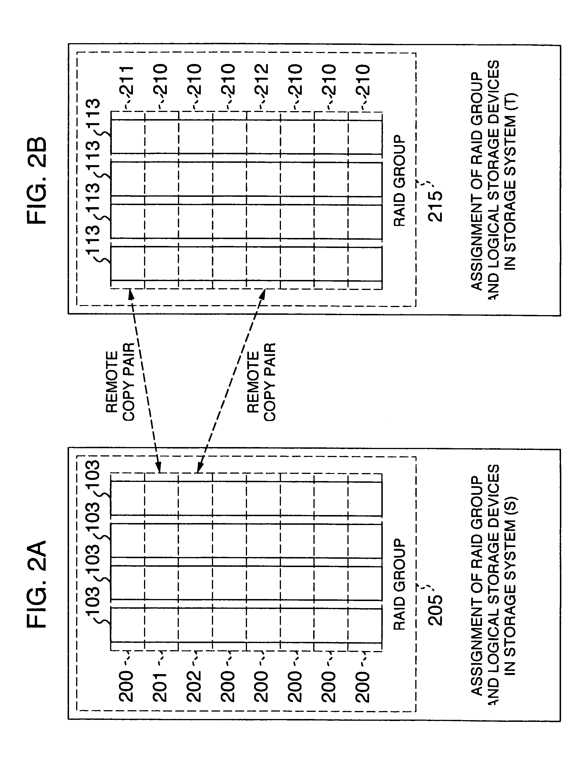
[0165]In the third embodiment, a logical volume is distributively arranged / rearranged on a plurality of RAID groups.

[0166]FIG. 9 shows the construction of a storage system according to the third embodiment.

[0167]As shown, a storage system 1001 according to the present embodiment has a controller 1011 and a plurality of storage devices 1031 which form a plurality of RAID groups 205. The storage system 1001 is connected to a CPU 1201.

[0168]Like the storage system 100 shown in conjunction with the first embodiment mentioned above, the storage system 1001 is a storage system in which the controller 1011 manages a logical volume 104 by means of logical storage devices 200 described and shown in conjunction with the first embodiment and holds logical volume information tables 300 and logical storage device information tables 310 (see FIG. 3) therein.

[0169]As mentioned above, the logical storage devices 200 are obtained by dividing, for each of the RAID groups 205, the...


PUM


Abstract

In a storage system, a logical volume is divided into a plurality of small areas called logical storage devices and only such an area designated by a user is made an object of remote copying or migratory copying. Also, there is provided a unit for forming a logical volume from any logical storage device of any RAID group. Thereby, the reduction of the deterioration in performance at the time of remote copying, the reduction of a storage area to be assigned to a secondary site as a copy destination, the shortening of a time required for migratory copying and the assignment of any area of a logical volume on any RAID group are enabled.

Description

[0001]This is a continuation application of U.S. Ser. No. 09 / 376,991, filed Aug. 19, 1999 now U.S. Pat. No. 6,681,303.BACKGROUND OF THE INVENTION[0002]The present invention relates to a technique of copying of date between storage systems without the intervention of a CPU and a technique of arrangement / rearrangement of a logical volume on RAID groups in a storage system. Further, the present invention relates to a storage system in an information processing system or the like and relates to a computer system having a function of generating a copy of data stored in a volume.[0003]A technique of remote copying exists as one of techniques in which the copying of data is performed between storage systems.[0004]In the remote coping, the writing of data in a duplicated manner is made without the intervention of a CPU between a plurality of storage systems located at physically remote places. Therein, storage systems respectively arranged at primary and secondary sites are connected by a d...

Claims


Application Information

Patent Timeline
Patent Type & Authority Patents(United States)
IPC IPC(8): G06F13/20G06F11/14G06F11/20
CPCG06F11/1451G06F11/2082G06F11/2064
Inventor WATANABE, HARUAKIARAI, KOUJINAKAMURA, KATSUNORIOEDA, TAKASHIYAMAMOTO, AKIRAYAMAGAMI, KENJI
Owner HITACHI LTD
Why Eureka
Try Eureka