Method for automated generation and assembly of specifications documents in CADD environments

a technology of cadd environment and specification document, applied in the direction of instruments, computing, electric digital data processing, etc., can solve the problems of affecting the project and all parties, the process of specification development is susceptible to human error and inaccuracy, and the interns and junior designers are typically not skilled in specifications preparation

Inactive Publication Date: 2007-01-09
GILLIG ROBERT B
View PDF25 Cites 13 Cited by
  • Summary
  • Abstract
  • Description
  • Claims
  • Application Information

AI Technical Summary

Problems solved by technology

In spite of the critical role Specifications play in the successful completion of a Project, Interns and Junior Designers typically are not skilled in Specifications preparation, often by their own choice, as it is commonly seen as unglamorous drudgery.
Specifications are produced through a laborious process of cataloguing each Drawing Entity in the Drawings and creating a customized Specification text to be associated with it.
The process of Specifications development is susceptible to human error and inaccuracy, with potential consequences to the Project and all parties associated with it of delays, cost overruns, and / or litigation.
The process of creating Specifications Documents can be tedious and time-consuming and on a Project-to-Project basis can be highly redundant, but since each Project is at least slightly different, and since those differences cannot be assumed to be self-evident, it is incumbent upon the Specifier to essentially ‘start-from-scratch’ with each new Project.
This benefit is accrued incrementally over time, and the initial act of Specifications text creation may be equally as tedious and time-consuming as in conventional methods.
Updating a Drawing Entity in the central database causes every occurrence of that Entity to be updated throughout a Project or multiple Projects, which is otherwise a time-consuming task prone to human error.

Method used


Image

  • Method for automated generation and assembly of specifications documents in CADD environments
  • Method for automated generation and assembly of specifications documents in CADD environments
  • Method for automated generation and assembly of specifications documents in CADD environments

Examples


first preferred embodiment

[0061]Referring now to FIG. 3, which shows a detail drawing representative of the types of graphical drawings that in the aggregate comprise a Drawing, a number of which in turn comprise the graphical portion of a Project. The drawing of FIG. 3 contains a graphical depiction of a particular assembly 68, and a number of textual components, in this case, Drawing Notes. The upper-most Drawing Note 60 reads “Galv. Masonry Ties@ 24″ o.c. vert. (typ)”. A lead line 62 points to the area of the graphical depiction to which the Drawing Note refers. The next Drawing Note below Drawing Note 60 appears as Drawing Note 66, reading “½″ gypsum Wall Board on 1½″ stl. furring channels@ 24″ o.c. vert. (typ.)”.

[0062]In the prior art this graphical depiction was created by a CADD program, and the Drawing Notes are likewise contained within this same CADD program. Both the constituent parts of the graphical depiction, and the Drawing Notes are Drawing Entities in the prior art. Utilizing this same prior...


PUM


Abstract

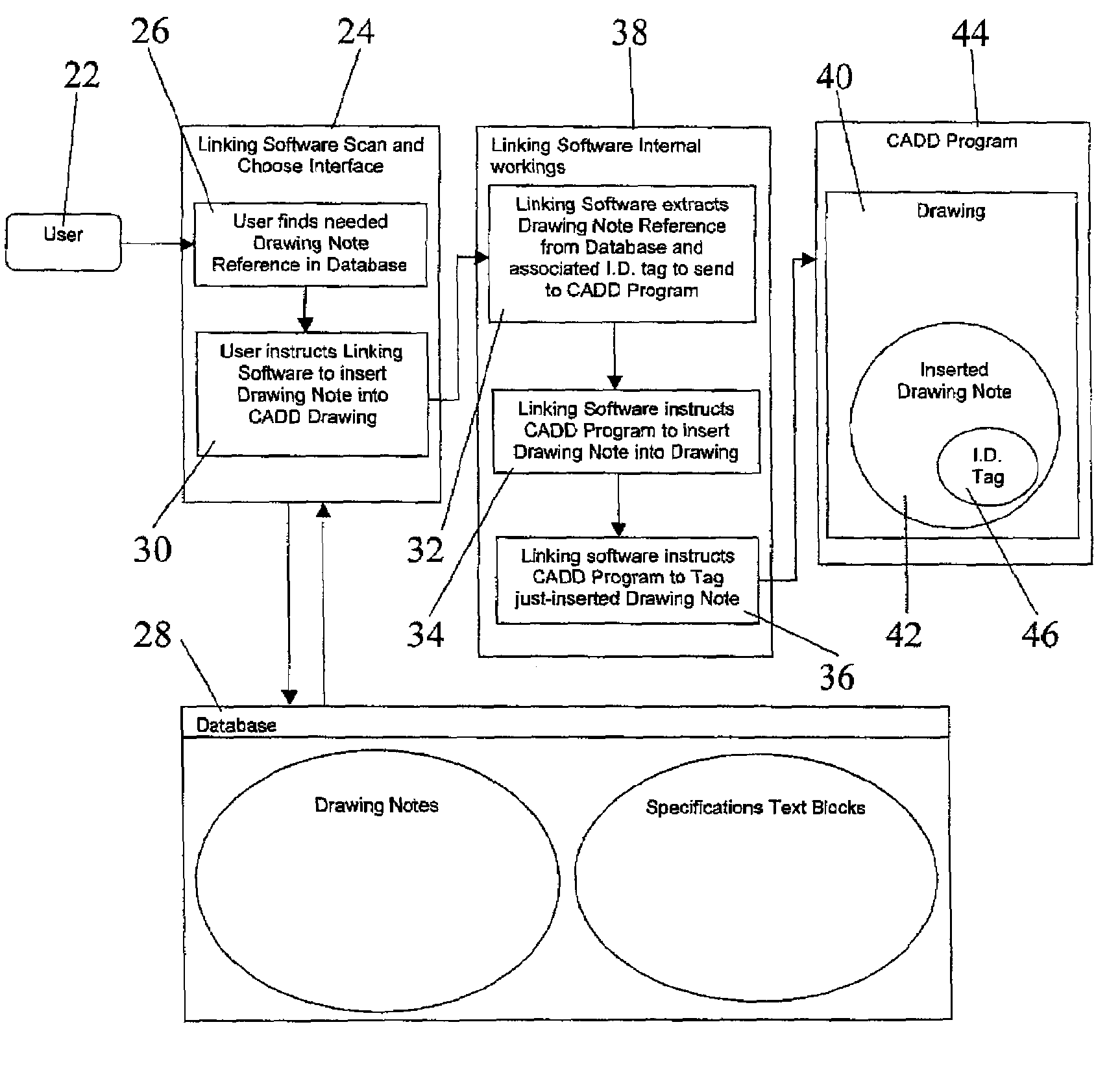
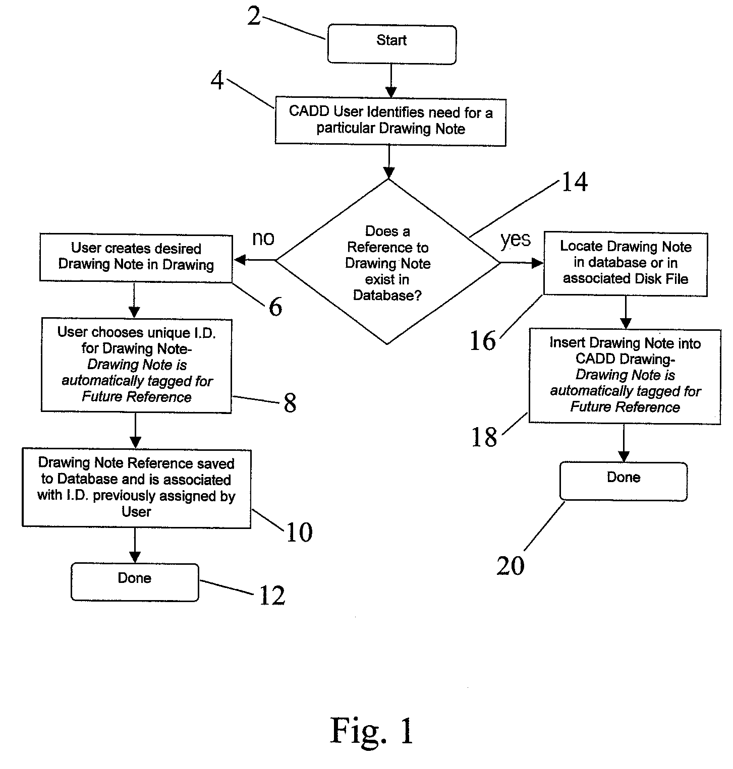
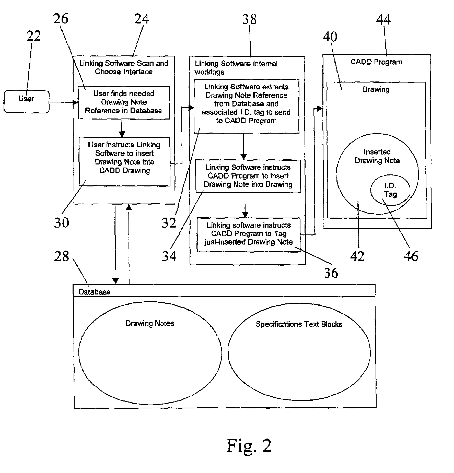
A method for automating the production of corroborative Textual Documentation for CADD-based Design and Engineering disciplines includes a computer-based system with Linking Software. The generation of CADD drawings creates an electronic database of unique graphical entities. The method creates subsequent drawings which may include some or all of the Drawing Entities stored in the database. An electronic link is effected between the Drawing Entities and the associated Specifications document text. Unique Drawing Entities within a CADD drawing are tagged with a unique identifier. Simultaneously, Specifications Text Blocks, each one comprising a subset of the complete Specifications Document, are identified. Each Drawing Entity in the database is uniquely linked to one or more Specifications Text Blocks. Subsequent use of the tagged Drawing Entity allows for the automatic re-use of the associated Specifications Text Block.

Description

PROSECUTION HISTORY[0001]This application claims priority based on U.S. application Ser. No. 09 / 626,803, filed on Jul. 27, 2000 now U.S. Pat. No. 6,993,708 by the same inventor as the present application.BACKGROUND OF INVENTION[0002]In the creation of Architectural, Engineering, or other design-services based fabrications, it is typically required that both graphical and textual descriptions of the final product be produced. Graphical descriptions (‘Drawings’) are typically produced in Computer-Aided Design and Drafting (‘CADD’) software programs such as AutoCAD, and textual descriptions (‘Specifications’) are produced in text processing programs such as Microsoft Word. Drawings and Specifications are complimentary—Drawings typically delineate such information as size, shape, volume, material types, and details of fabrication whereas Specifications typically describe acceptable methods of assembly and standards of quality for the fabrication process as a whole or within its constitu...

Claims


Application Information

Patent Timeline
Patent Type & Authority Patents(United States)
IPC IPC(8): G06F17/00
CPCG06F17/50G06F30/00
Inventor GILLIG, ROBERT B
Owner GILLIG ROBERT B
Why Eureka
Try Eureka