
Adjustable ladder stabilizer

a technology of adjustable and lateral movement, which is applied in the direction of ladders, building construction, construction, etc., can solve the problems of difficult assembly, difficult assembly, and difficult production, and achieve the effects of convenient installation, convenient production, and convenient us

Inactive Publication Date: 2007-01-16
BLEHM BERLE G
View PDF8 Cites 53 Cited by
  • Summary
  • Abstract
  • Description
  • Claims
  • Application Information

AI Technical Summary

Benefits of technology

[0012]The adjustable ladder stabilizer provides a ladder support assembly that is relatively easy to produce, easy to install, easy to use, and above all, safe. This stabilizer can be quickly and easily adjusted to provide support on a variety of level or uneven surfaces including floors, patios, ground, pavement, etc.

Problems solved by technology

However, accidents frequently occur because of lateral tipping or slipping movements.
Accidents caused by such lateral movement of the ladder are particularly likely when the climber is at the top of the ladder.
Each attempt has involved relatively complex structures to be added to the ladder.
Most devices are not easily attached to the ladder and once attached, add significant weight to the ladder.
These channel members alone add prohibitive weight to the ladder.
One other disadvantage of the elongated channel member of U.S. Pat. No. 4,244,446 is the channel can be a collector of dust or dirt or soil making the adjustment of such a device cumbersome.
Extension ladders are most frequently utilized (and often stored) outdoors and subject to accumulating dirt on the rails.
While this device does not have the complexity of previous ladder support devices, it utilizes a clamp to attach the support device to the outside edges of the ladder rails.
This presents a major problem to the user.

Method used


Image

  • Adjustable ladder stabilizer
  • Adjustable ladder stabilizer
  • Adjustable ladder stabilizer

Examples


Embodiment Construction

)

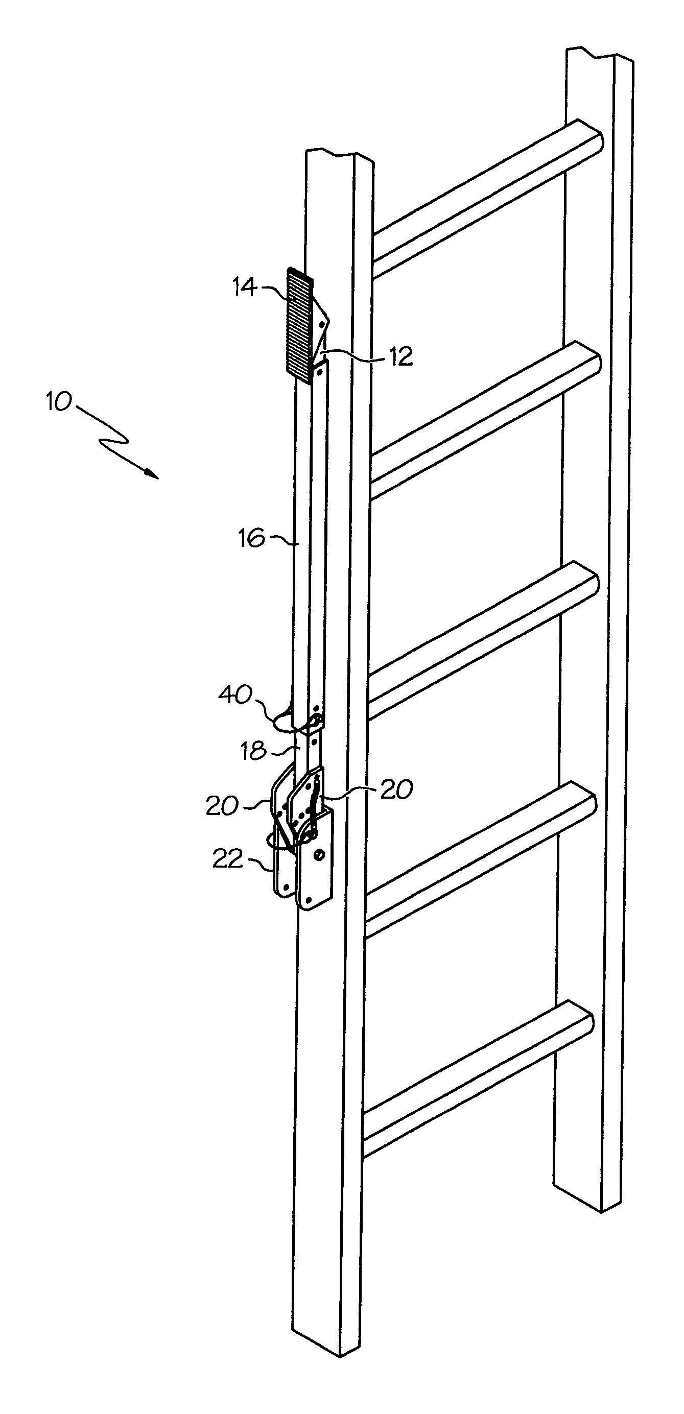
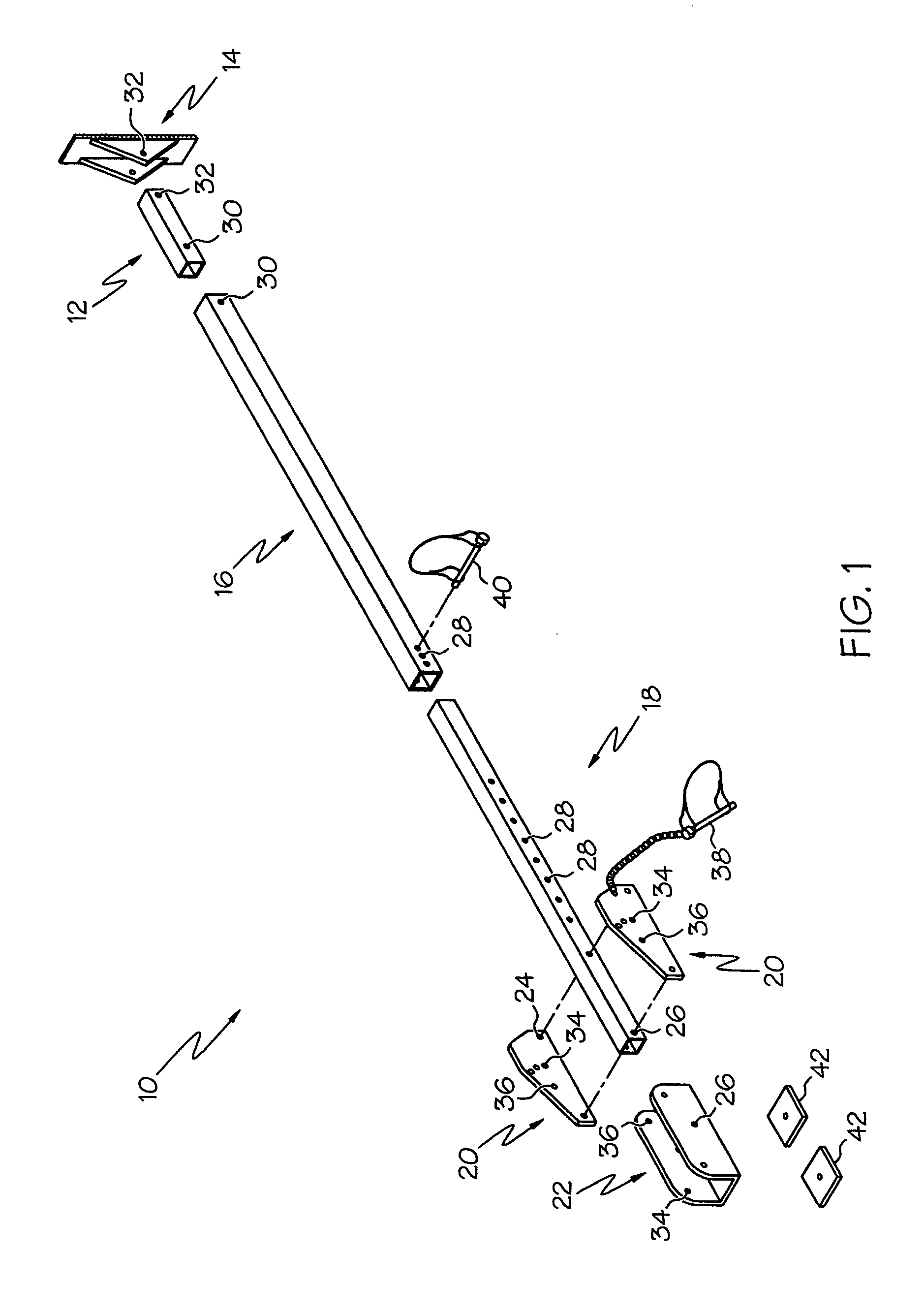
[0018]Referring to FIG. 1, which best shows the general features of a preferred embodiment of the invention, the lower support member 12 is attached to a base member 14 at one end and the support housing 16 at an opposite end. The attachment means are typically bolts (not shown) but any suitable attachment means will suffice. The support housing 16 is connected to the upper support member 18 via a locking pin 40 inserted through adjusting / affixing apertures 28.

[0019]Indexing plates 20 are secured to the upper end of the upper support member 18 typically by bolts (not shown) inserted through apertures 24. The upper support member 18 and index plates 20 are pivotally secured in channel bracket 22 by a bolt (not shown) through pivot apertures 26. The channel bracket 22 can best be described as a U-shaped bracket with a base section and two leg sections forming the U shape.

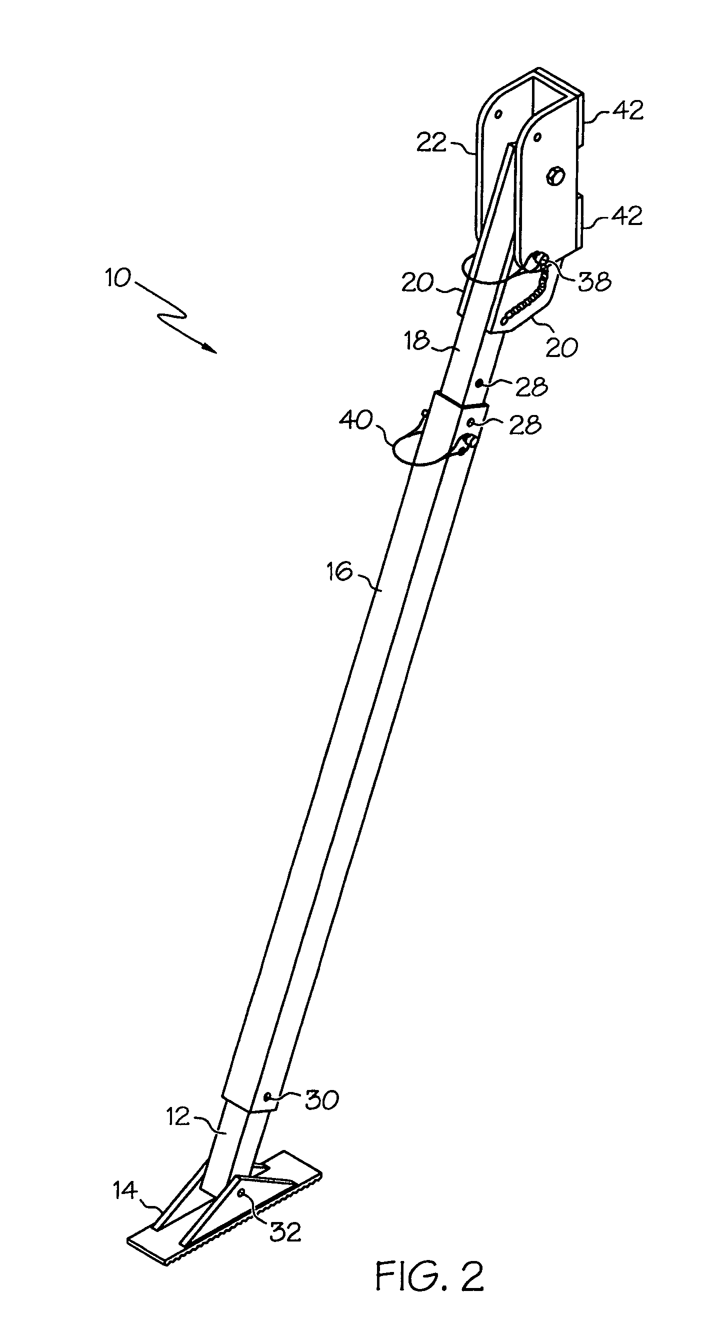
[0020]FIG. 2 is a perspective view of unattached ladder stabilizer 10 in support position. Quick release wire lock...


PUM


Abstract

An adjustable ladder stabilizer assembly composed of sturdy, lightweight components that can be temporarily or permanently affixed to the side rails of a ladder and adjusted to a variety of positions to provide lateral support. This stabilizer assembly can also be folded up and easily secured in a storage position to fit within the profile of a ladder when not in use.

Description

CROSS REFERENCE TO RELATED APPLICATIONS[0001]None.FIELD OF INVENTION[0002]This present invention relates in general to ladder support assemblies and in particular to assemblies attached to the sides of ladders to provide lateral support.BACKGROUND OF INVENTION[0003]Ladders, especially extension ladders, are very effective in allowing a person to reach a high, otherwise inaccessible position for painting, repair or other related tasks. Extension ladders are commonly used by workers in performance of their occupation as well as homeowners making repairs on their property. Ladders usually have a pair of leg members spaced apart by and connected to a series of parallel rungs. When properly placed on flat, stable ground, the ladder is usually relatively stable longitudinally, namely in the vertical plane that bisects the rungs.[0004]However, accidents frequently occur because of lateral tipping or slipping movements. If the ladder is not completely vertical the chances of it tipping late...

Claims


Application Information

Patent Timeline
IPC IPC(8): E06C7/00
CPCE06C7/423
Inventor BLEHM, BERLE G.
Owner BLEHM BERLE G
Features
  • Generate Ideas
  • Intellectual Property
  • Life Sciences
  • Materials
  • Tech Scout
  • Unparalleled Data Quality
  • Higher Quality Content
  • 60% Fewer Hallucinations
Learn More