Lighting unit and display device

Active Publication Date: 2007-01-16
SHARP KK
View PDF17 Cites 44 Cited by
  • Summary
  • Abstract
  • Description
  • Claims
  • Application Information

AI Technical Summary

Benefits of technology

[0043]The bonding steps are defined, whereby the manufacturing method offers excellent bonding efficiency. Namely, p

Problems solved by technology

However, the directivity of light of the LED is low, and light radially travels in forward and oblique directions at various angles.
This poses a problem in that the usage efficiency of light emitted by the LED and entering the light guide plate is low.
In this kind of lighting unit, light exhibiting a large angular distribution leaks out of the second light guide plate and degrades the contrast offered by the display device.
Moreover, there is a problem that a part o

Method used


Image

  • Lighting unit and display device
  • Lighting unit and display device
  • Lighting unit and display device

Examples


first embodiment

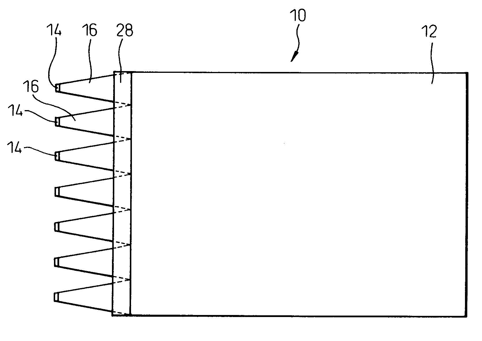
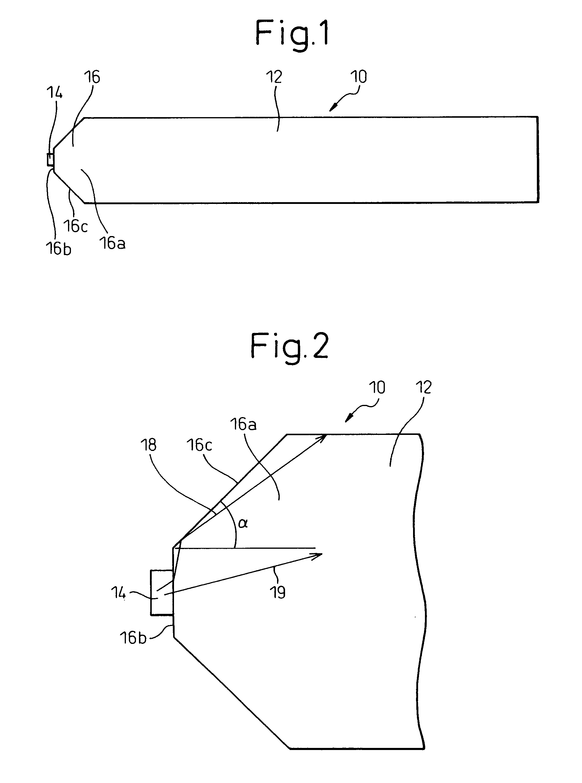
[0128]FIG. 1 is a schematic view showing a lighting unit 10 in accordance with a FIG. 2 is a partially enlarged view of the lighting unit 10 for explaining the operation of the lighting unit 10 shown in FIG. 1.

[0129]FIGS. 5 and 6 are schematic views showing an example of a display device including a lighting unit. In FIGS. 5 and 6, a display device 100 includes a lighting unit 102 and a display panel 104. In FIG. 5, the lighting unit 102 is a front light, and the display panel 104 is a reflective liquid crystal display panel. A polarizer 106 is arranged between the front light 102 and display panel 102. In FIG. 6, the lighting unit 102 is a backlight and the display panel 104 is a transmissive liquid crystal display panel. Polarizers 106 are arranged on both sides of the display panel 104. The lighting unit 10 to be described below is usable as the lighting unit 102 shown in FIG. 5 or FIG. 6 or any other lighting unit.

[0130]Referring to FIG. 1, the lighting unit 10 comprises a ligh...

second embodiment

[0154]FIG. 28 is a schematic view showing a liquid crystal display device in accordance with the present invention. FIG. 29 is a sectional view of the liquid crystal panel included in the liquid crystal display device shown in FIG. 28. The liquid crystal display device 40 comprises a liquid crystal panel 42, a lighting unit 44, a polarizer 46, and a low refractive index layer 48. Preferably, the liquid crystal panel 42 is of a reflective type and of a vertical alignment type (VA type).

[0155]In FIG. 29, the liquid crystal panel 42 has a liquid crystal 42c arranged between a pair of glass substrates 42a and 42b. One of the glass substrates 42a includes a common electrode 42d and a vertical alignment layer 42e, and the other glass substrate 42b includes pixel electrodes 42f and a vertical alignment layer 42g. Consequently, the liquid crystal molecules are aligned generally perpendicularly to the surfaces of the substrates when no voltage is applied, and the liquid crystal molecules are...

third embodiment

[0193]FIG. 63 shows a liquid crystal display device in accordance with the present invention. A liquid crystal display device 70 comprises a light source 72, a light guide plate 74 on which light emitted by the light source 72 falls, a liquid crystal panel 76 of a reflective vertical alignment type, and a polarizer 78 interposed between the light guide plate 74 and liquid crystal panel 76. A low-refractive-index layer 80 is interposed between the light guide plate 74 and the polarizer 78. The refractive index of the low-refractive-index layer 80 is higher than that of air but lower than that of the light guide plate 74.

[0194]The light guide plate 74, the polarizer 78, and the liquid crystal panel 76 are bonded to one another using an adhesive, a glue, or a bond. The low-refractive-index layer 80 comprises an adhesive, glue, or bond. The refractive index of the adhesive is nominally 1.48, but the substantial refractive index is made 1.47 or less by uniformly containing air in the adh...


PUM


Abstract

A lighting unit and a liquid crystal display device which can improve the efficiency of usable light. The lighting unit includes a light source, a light guide plate, and a truncated pyramid located between the light guide plate and the light source. The truncated pyramid has a base, a top smaller than the base, and a slope linking the base and the top. The light source is placed in close contact with the top of the truncated pyramid, and the light guide plate is placed in close contact with the base of the truncated pyramid. Light is propagated from a light emitting part of the light source to the light guide plate without passing through any air layer. Also, an unnecessary light removing structure is provided in the light guide plate near the incidence surface thereof.

Description

BACKGROUND OF THE INVENTION[0001]1. Field of the Invention[0002]The present invention relates to a lighting unit and a display device.[0003]2. Description of the Related Art[0004]For example, a display device such as a liquid crystal display device includes a lighting unit referred to as a front light or a backlight. The lighting unit includes a light source and a light guide plate. Light emitted by the light source enters the light guide plate. The light is propagated through the light guide plate while being repeatedly totally reflected within the light guide plate. The light leaves the light guide plate toward a display panel by means of a light discharging mechanism such as a set of prisms.[0005]A cold cathode tube (fluorescent lamp) is used as the light source. The cold cathode tube is located at the side of the light guide plate together with a generally U-shaped reflector. Light emitted by the cold cathode tube and reflected by the reflector falls on the light guide plate.[00...

Claims


Application Information

Patent Timeline
IPC IPC(8): F21V7/04F21V8/00G02B6/00F21Y101/02G02F1/13357
CPCG02B6/0028G02F1/133615G02B6/0038G02B6/003G02B6/00G02B6/0056G02F1/1335
Inventor SUZUKI, TOSHIHIROHAMADA, TETSUYASUGAWARA, MARIKOBAYASHI, TETSUYAHAYASHI, KEIJI
Owner SHARP KK
Why Eureka
Try Eureka