Connector structure

a technology of connecting structure and connector, which is applied in the direction of coupling contact members, coupling device connections, contact members penetrating/cutting insulation/cable strands, etc., can solve the problems of increasing the burden on the connection cable, damage to the outer skin of the connection cable or on the conductor itself, and difficulty in routing the connection cable, etc., to simplify the connection process of the connection cable, simplify the connection work, and simplify the effect of the work

Inactive Publication Date: 2007-01-16
SMK CORP
View PDF5 Cites 3 Cited by
  • Summary
  • Abstract
  • Description
  • Claims
  • Application Information

AI Technical Summary

Benefits of technology

[0012]Therefore, in case of said connector, the connection cables that are connected to the connector extend in parallel with the circuit board surface. Moreover, a plurality of cables such as in the case of a flat cable is laid crosswise relative to a plurality of connection positions in order to electrically connect desired cables among the cables laid crosswise with desired connection. This transmits electrical signals from each desired cable to each desired terminal of the contact part, so that it is possible to arrange the signal pattern freely from each cable obtained from the contact part without rearranging the cable positions.
[0026]Moreover, the invention makes it possible to simplify the connection works between the cables and terminals by providing a housing cover with IDC protrusions formed at specified locations on the cable carrying side of the housing. This causes the cover to latch with the housing and electrically connect the desired cables and the desired terminals by means of crimping or IDC. Similarly, as the housing cover consists of the cover main body and the spacers and the cover can be latched with the housing after the spacers are placed on the desired connection parts and the desired cables, the invention makes it possible not only to connect the desired cables with the desired connection parts more easily, but also to simplify the works further, providing a wider range of applications for the process and making it easier to use individual parts by means of automating the process of placing the spacers in desired positions in the combination of the cover main body and the spacers.INDUSTRIAL APPLICATION

Problems solved by technology

A problem with connectors of prior art for electrically connection cables with wiring patterns of circuit boards is that the direction of insertion of the connection cables into the connector socket is perpendicular to the circuit board.
As a consequence, the connection cable is bent or twisted when it is connected to a circuit board in a device, which presents a problem that it is difficult to route the connection cable when there is not enough space above the circuit board to which the connectors are to be connected.
There are also problems that damages tend to occur on the outer skin of the connection cables or on the conductors themselves if the connection cables are used for prolonged periods of times maintaining sharp bends.
In case of routing the connection cables as described above, the connection cables have to be bent almost perpendicularly in parallel with the circuit board as shown in FIG. 7, if in case the cables are to be placed in the same direction as the layout direction of the circuit board pattern (i.e., the layout direction of the connection cables is perpendicular to the circuit board layout pattern), so that it presents not only a problem that the burden on the connection cables increases due to the bending but also a problem that the connection cables cannot be laid out smartly as the connection cables on both ends having different actual layout route lengths despite the fact that all connection cables have the same length.

Method used


Image

  • Connector structure
  • Connector structure
  • Connector structure

Examples


example 1

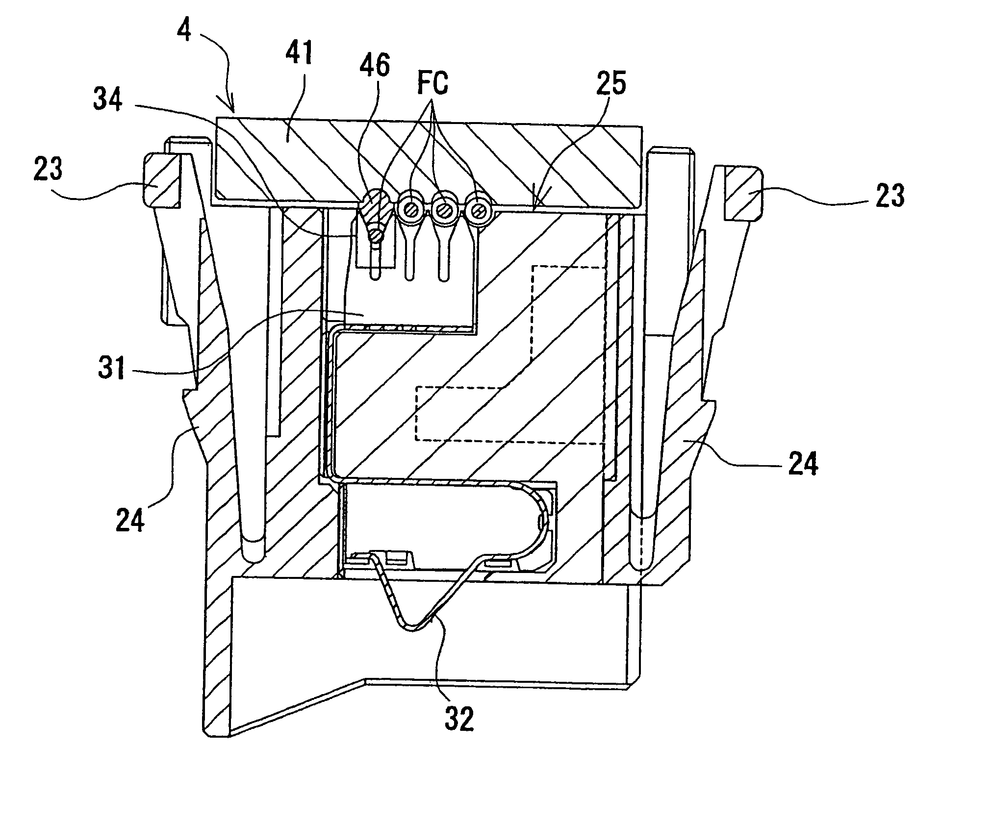
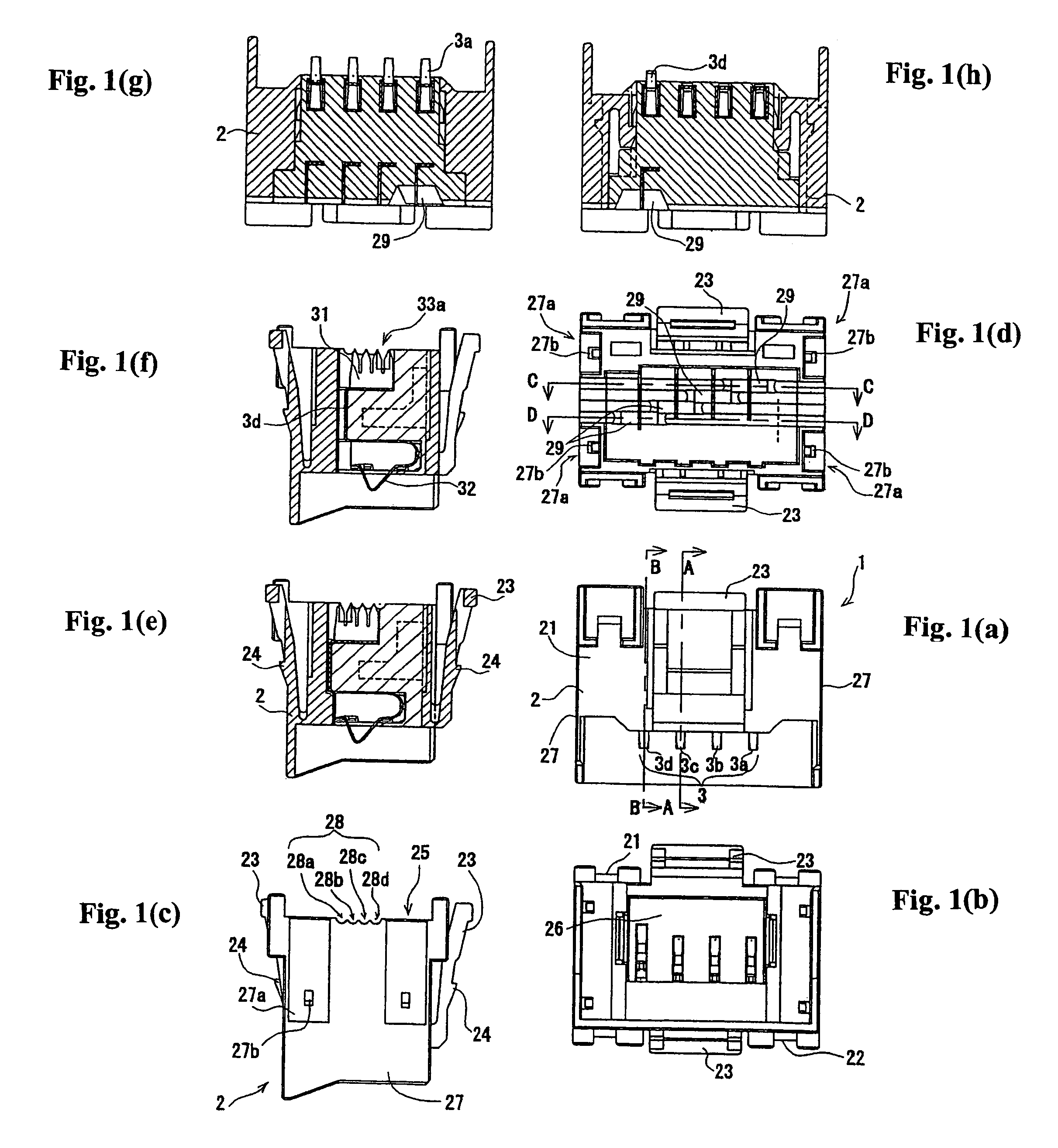
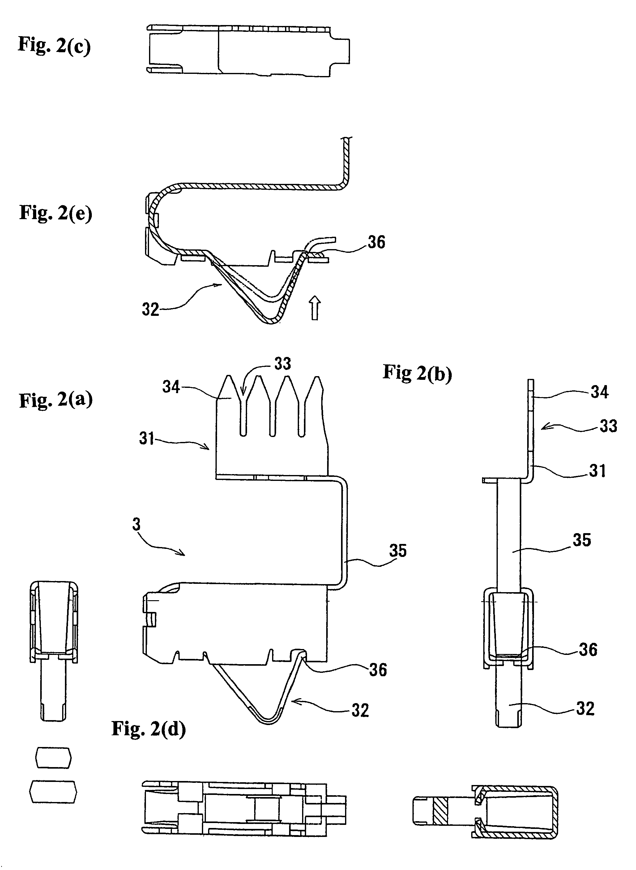
[0054]A preferred embodiment of the invention will be described in the following referring to the accompanying drawings. FIG. 1 shows a connector according to the invention, where (a) is a front description view of the connector according to the invention, (b) is its bottom description view, (c) is its left side description view, (d) is its plan description view, (e) is an A—A cross-sectional description view, (f) is a B—B description view, (g) is a C—C description view, and (h) is a D—D description view. FIG. 2 shows the connector's terminal according to the invention, where (a) is a front description view of the terminal according to the invention, (b) is its right side description view, (c) is its plan description view, (d) is its bottom description view, and (e) is a B—B cross-sectional description view. FIG. 3 shows the connector's cover according to the invention, where (a) shows a front description view of the housing cover, (b) is its bottom description view, (c) is its left...


PUM


Abstract

A contact construction requiring minimum space above a connector allowing installation of a connection cable on a circuit board in a layout direction of contacts that provides increased freedom in wiring / board design. A bottom surface of the housing forms a mounting surface of the circuit board while a top surface forms a cable layout surface for laying out the connection cable in the surface direction of the circuit board. A bottom end of a terminal in the housing protrudes toward the circuit board side to form a contact part to connect with the circuit board, and the top end forms a connection part to connect with the connection cable. A plurality of terminals is provided in a row in the housing, a plurality of wires is laid out on the cable layout surface in the circuit board direction, ensuring each connection cable is electrically connected to the desired terminal.

Description

INCORPORATION BY REFERENCE[0001]The present application claims priority under 35 U.S.C. §119 to Japanese Patent Application No. 2004-169354 filed on Jun. 8, 2004. The content of the application is incorporated herein by reference in its entirety.[0002][0003]1. Field of the Invention[0004]The invention relates to a connector that electrically connects with a circuit board, more specifically, a connector that electrically connects a group of cables consisting of a plurality of cables or a flat cable with another member.[0005]2. Description of the Related Art[0006]Crimping connectors and insulation displacement connectors (“IDC”) are widely used. For example, IDC such as the one shown in FIG. 6 have been widely used in the inside of electronic equipment.[0007]An insulation displacement connector (“IDC”) 100 shown in FIG. 6 is a connector plug, wherein connection terminals 101 provided on the insulation connector 100 fit with connector pins 112 when the connector plug fit with a plurali...

Claims


Application Information

Patent Timeline
Patent Type & Authority Patents(United States)
IPC IPC(8): H01R4/24H01R13/24
CPCH01R4/2433H01R12/675H01R13/2442
Inventor MIYOSHI, OSAMU
Owner SMK CORP
Why Eureka
Try Eureka