Apparatus and method for detecting pipeline defects

a technology for detecting apparatus and pipelines, applied in the direction of fluid tightness measurement, instruments, structural/machine measurement, etc., can solve the problems of inability to accurately, stop, pan and tilt to get more detailed information, and insufficient lighting to identify defects

Inactive Publication Date: 2007-01-16
OYO CORP US
View PDF19 Cites 81 Cited by
  • Summary
  • Abstract
  • Description
  • Claims
  • Application Information

AI Technical Summary

Benefits of technology

[0009]An apparatus and method is disclosed for inspecting or scanning the interior of a sewer line (or other similar pipeline) that eliminates the need for and consequent delay associated with stopping for pan and tilt closer inspection and that provides objective inspection. Moreover, an apparatus and method is disclosed that provides a real-time digitized and synchronous forward view and a 360 degree peripheral or side-scan view of a pipeline. The continuous digitized real time images may be saved for later evaluation.

Problems solved by technology

If the operator, for whatever reason, does not visually identify an area of potential interest or concern (cracks, roots, etc.) in the forward looking view, the opportunity to stop, pan, and tilt to get more detailed information is lost.
Common problems with known commercial systems have included inability to accurately gauge the location of a detected defect, insufficient lighting to identify a defect, distortion of image, inadvertent missing of defects, uneven quality and subjective defect classification, and requirement for burdensome review of volumes of video tapes after the inspection in an effort to decipher the video tapes and to distinguish defects from shadows.
Most typically, use of known commercial systems can result in oversight of critical cracks and other defects in the pipeline.
However, this device does not appear to include a digital forward view of the pipeline.

Method used


Image

  • Apparatus and method for detecting pipeline defects
  • Apparatus and method for detecting pipeline defects
  • Apparatus and method for detecting pipeline defects

Examples


Embodiment Construction

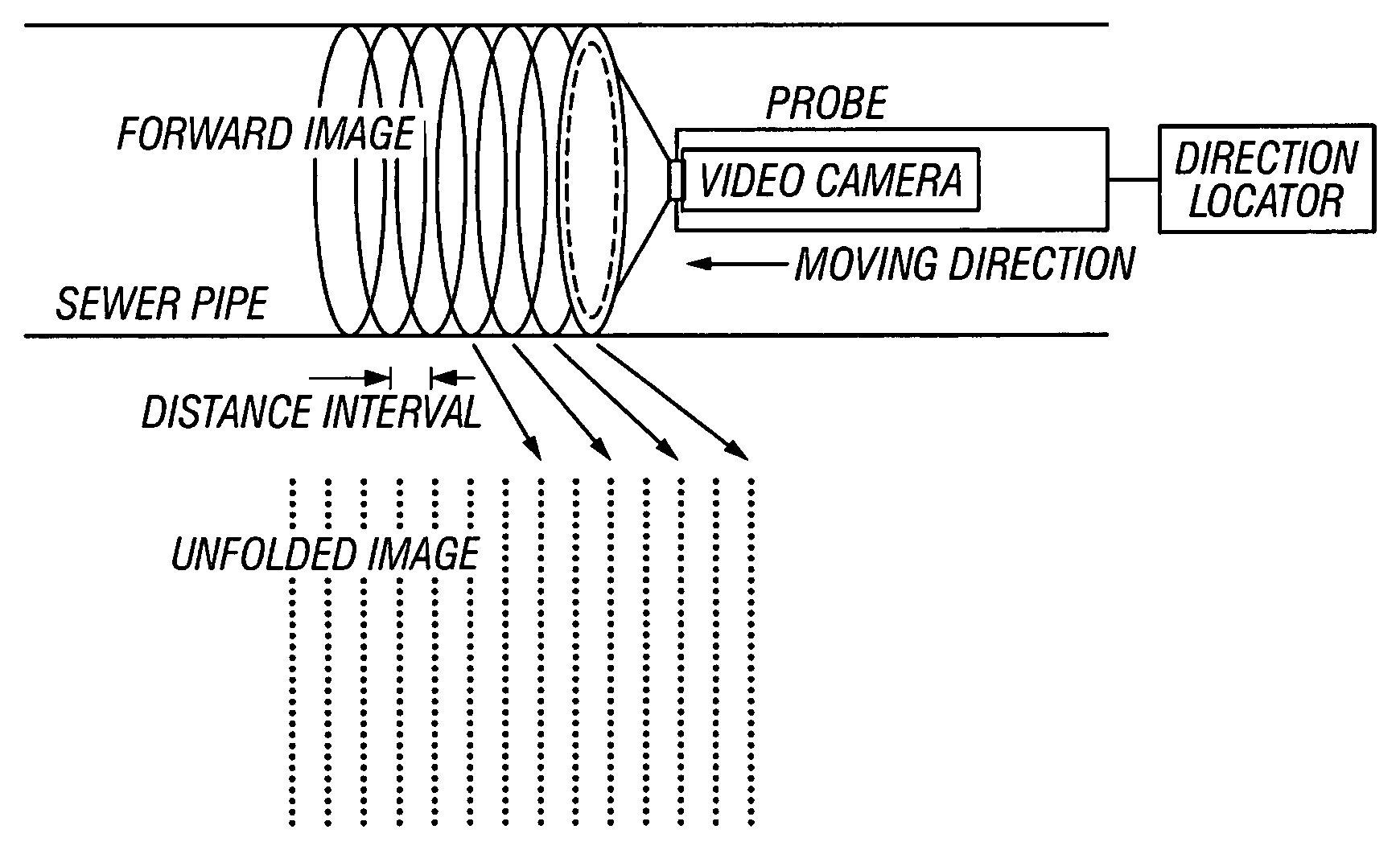
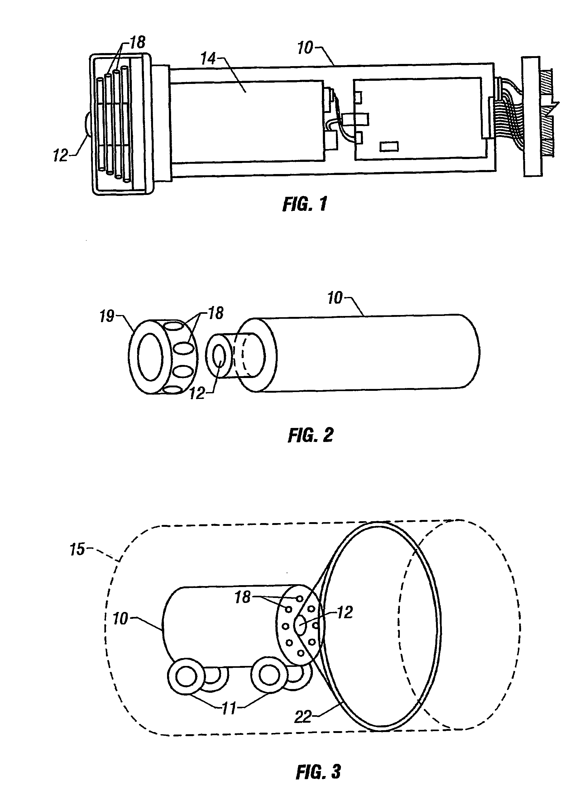
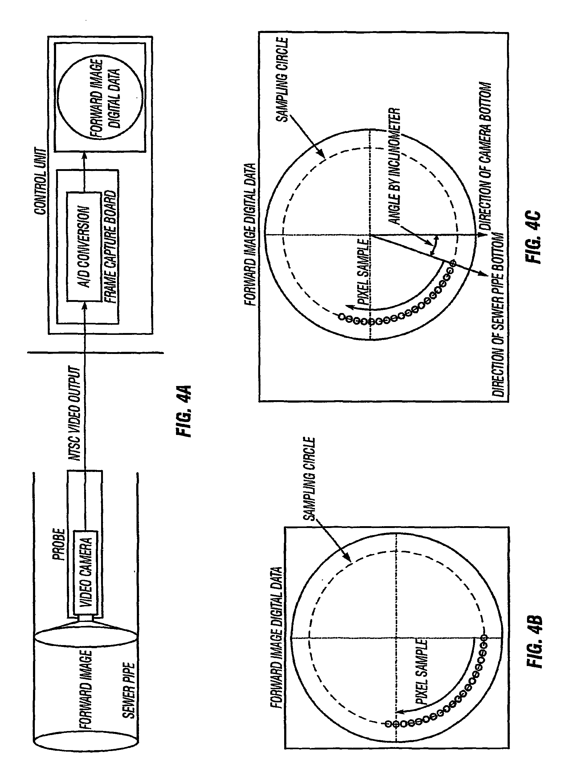
[0023]An apparatus and method are disclosed for scanning the interior of a conduit, pipe or pipeline to determine defects in the interior of such pipeline. Such “defects” as the term is used herein is understood to include joint separations, corrosion, cracks, depressions, or crushes and the like in the pipeline, and even obstructions or projections (such as roots or debris) and the like in or into the interior of the pipeline, and also any other visible feature, characteristic, or condition of the pipeline that may be of concern or interest for inspection or determination. The pipelines suitable for inspection with the apparatus and method of the invention are preferably positioned substantially horizontally or at least off of vertical. The advantages of the invention may be especially appreciated with pipelines that are buried underground and with pipelines that transport liquids, gases, or slurries, such as sewer lines. Further, the advantages of the invention may be especially a...


PUM

PropertyMeasurementUnit
wide anglesaaaaaaaaaa
diameteraaaaaaaaaa
diameteraaaaaaaaaa

Abstract

An apparatus and method are disclosed for scanning and detecting defects in sewer and similar pipelines that eliminate the need to stop and pan-and-tilt areas of concern. In the method of the invention, a pipeline (15) inspection probe (10) of the apparatus of the invention comprising a CCD camera (14) with fish-eye lens (12) travels through the pipeline (15) on a self-propelled tractor automatically collecting data and transmitting it to a computer to provide a real-time display of the pipeline (15) interior with quasi three-dimensional information for effective and quick data analysis and management. The data includes digitized forward views and unfolded 360 degree laid-flat side-san (22) views of the pipeline (15) interior. Additionally, the digitized data may be stored for further analysis, tabulation, and for use with pipeline infrastructure maintenance software.

Description

RELATED APPLICATION[0001]This application claims priority to U.S. Provisional Patent Application No. 60 / 207,784, filed May 30, 2000.BACKGROUND OF THE INVENTION[0002]1. Field of the Invention[0003]This invention relates to apparatuses and methods for inspecting the interior of conduits and pipes, particularly pipelines, such as sewers, air ventilation ducts, or liquid or gas transport pipelines, and locating defects such as corrosion, joint separations, cracks, depressions, or crushes in same, as well as roots, debris, blockages, and the like. More specifically, this invention relates to viewing devices and methods for movably scanning the interior of pipes or pipelines and to the collection of data for analysis and interpretation of the results of such scanning to evaluate the condition of the pipelines and the location of any defects in the pipelines.[0004]2. Description of Relevant Art[0005]As used herein, the term “pipeline” or “pipelines” shall be understood to include conduits,...

Claims


Application Information

Patent Timeline
Patent Type & Authority Patents(United States)
IPC IPC(8): G01N21/88G01N15/00G01B11/24G01M3/00G01M3/38G01N21/954
CPCG01N21/954G01N2021/9544
Inventor SHIMA, HIROMASAKARASAKI, KENZIISELEY, DAVID THOMASGOEBUCHI, TORUSANO, KOIINUMA, HIROYUKI
Owner OYO CORP US
Why Eureka
Try Eureka