Optical head and optical recording/reproducing device using it and aberration correction method

a technology of optical recording/recording device and optical head, which is applied in the direction of digital signal error detection/correction, instruments, recording signal processing, etc., can solve the problems that the optical head with the foregoing configuration cannot be used for multi-layer optical recording medium, and the occurrence of aberration due to tilt of optical recording medium becomes a problem, etc., to achieve stable recording

Inactive Publication Date: 2007-01-16
PANASONIC CORP
View PDF24 Cites 14 Cited by
  • Summary
  • Abstract
  • Description
  • Claims
  • Application Information

AI Technical Summary

Benefits of technology

[0015]With this configuration of the optical head, it is possible to precisely correct an aberration that occurs due to a tilt of an optical recording medium even when recording and reproducing are carried out with respect to optical recording media with different substrate thicknesses, for instance, layers of a multi-layer optical recording medium, optical recording media of different types, and single-layer optical recording media having variation in their substrate thickness. Therefore, this makes it possible to perform stable recording and reproducing.
[0023]Still further, the foregoing configuration of the optical head of the present invention preferably further includes a substrate-thickness-related-aberration correcting means for correcting an aberration that occurs due to a deviation of the substrate thickness of the optical recording medium from a standard value of the substrate thickness. Further, in this case, it is preferable that the substrate-thickness-related-aberration correcting means includes: a positive lens group and a negative lens group disposed in an optical path; and a means for varying a lens distance between the positive lens group and the negative lens group. This preferable example makes it possible to correct an aberration that occurs relating to the substrate thickness of the optical recording medium, not only when light outgoes but also when light returns, thereby making it possible to perform stable recording and to obtain stable control signals and stable reproduction signals. Further, in this case, it is preferable that the substrate-thickness-related-aberration correcting means is formed with an optical element. The optical element includes a pair of substrates having transparent conductive thin films, respectively, and a phase shifting layer interposed between the pair of substrates. A pattern capable of correcting an aberration that occurs relating to the substrate thickness of the optical recording medium is formed on one of the conductive thin films. This preferable example makes it possible to omit all of the positive lens group, the negative lens group, and the means for varying a lens distance between the positive lens group and the negative lens group, thereby allowing the optical head to be downsized. In this case, it further is preferable that the phase shifting layer is made of liquid crystal. Further, in this case, it is preferable that the tilt-related-aberration correcting means and the substrate-thickness-related-aberration correcting means are formed with one optical element. The optical element includes a pair of substrates having transparent conductive thin films, respectively, and a phase shifting layer interposed between the pair of substrates. A pattern capable of correcting an aberration that occurs relating to the substrate thickness of the optical recording medium is formed on one of the conductive thin films. A pattern capable of correcting an aberration that occurs due to the tilt of the optical recording medium is formed on the other conductive thin film. This preferable example makes it possible to, using one optical element, correct a coma that occurs due to a tilt of the optical recording medium and a spherical aberration that occurs relating to the substrate thickness of the optical recording medium at the same time. Therefore, by incorporating the optical element in the optical head, the optical head can be downsized. In this case, it further is preferable that the phase shifting layer is made of liquid crystal.

Problems solved by technology

However, in an optical recording / reproducing device of a high-density optical recording medium using the foregoing blue laser, margins in recording and reproducing are extremely narrow, and hence, the occurrence of an aberration due to a tilt of an optical recording medium becomes a problem.
However, the optical head with the foregoing configuration cannot be used for a multi-layer optical recording medium in which information is recorded at a density higher than that in a DVD.
Therefore, a problem occurs in open loop control such that not an aberration that occurs due to a tilt of an optical recording medium but a tilt of an optical recording medium is detected, and an objective lens is tilted according to the tilt.

Method used


Image

  • Optical head and optical recording/reproducing device using it and aberration correction method
  • Optical head and optical recording/reproducing device using it and aberration correction method
  • Optical head and optical recording/reproducing device using it and aberration correction method

Examples


first embodiment

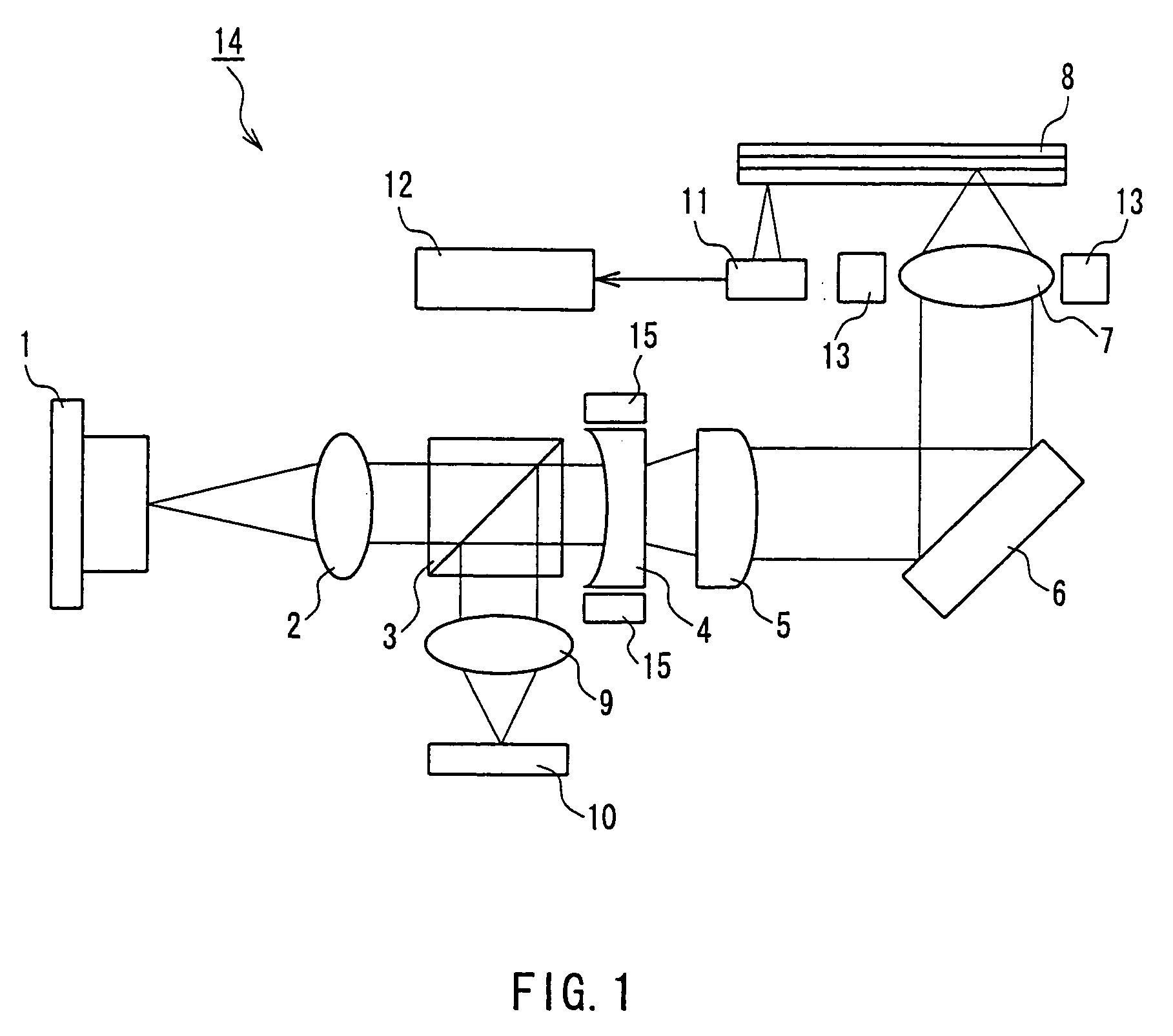
[0038]FIG. 1 is a schematic view illustrating an optical head according to a first embodiment of the present invention.

[0039]In FIG. 1, 1 denotes a light source, and a GaN-type semiconductor laser element (wavelength: 405 nm), for instance, is used as the light source 1. This light source 1 emits a coherent light for recording and reproducing to a recording layer of the optical recording medium 8. 2 denotes a collimator lens, and this collimator lens 2 is a lens for converting divergent light emitted from the light source 1 into parallel light. 3 denotes a beam splitter, and this beam splitter 3 is an optical element that transmits approximately 50% of light incident thereon and reflects approximately 50% of the same. 4 denotes a concave lens as a negative lens group, and this concave lens 4 is a lens intended to convert light that first has been converted into parallel light by the collimator lens 2 into divergent light again. 5 denotes a convex lens as a positive lens group, and t...

second embodiment

[0058]FIG. 5 is a schematic view illustrating an optical head according to a second embodiment of the present invention.

[0059]As shown in FIGS. 1 and 5, an optical head 16 (FIG. 5) of the present embodiment is different from the optical head 14 (FIG. 1) of the first embodiment described above only in that the optical head 16 includes a substrate thickness detecting means for detecting information concerning a substrate thickness of an optical recording medium 8, and the configuration of the optical head 16 except for the foregoing aspect is identical to that of the first embodiment. Therefore, herein the details of the present embodiment that are not specifically described are considered to be identical to those of the first embodiment described above, and the constituent members denoted with the same reference numerals as those in the first embodiment are considered to have the same functions as those of the first embodiment unless they are described specifically.

[0060]In FIG. 5, 5...

third embodiment

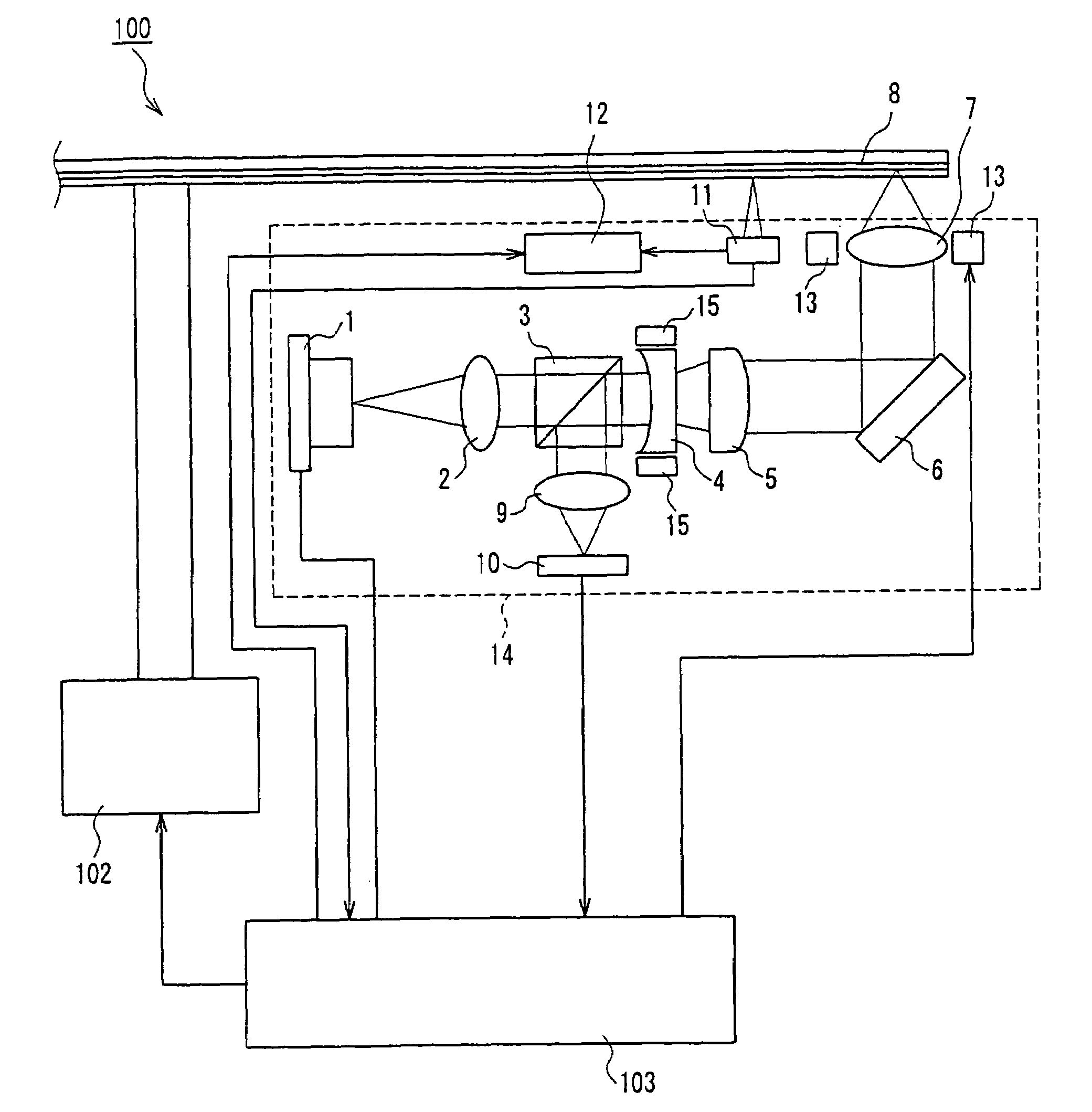
[0092]FIG. 10 is a view schematically illustrating an optical recording / reproducing device according to a third embodiment of the present invention.

[0093]The optical recording / reproducing device of the present embodiment is a device for recording and reproducing signals to and from a single-layer or multi-layer optical recording medium. As shown in FIG. 10, an optical recording / reproducing device 100 according to the present embodiment includes the optical head 14 of the first embodiment described above, a motor 102 for rotating the optical recording medium 8, and a processing circuit 103. Though the optical head of the first embodiment described above is used here, the optical head of the second embodiment described above may be used instead. Since the optical head is the same as that described in conjunction with the first embodiment, duplicate descriptions thereof are omitted.

[0094]Next, an operation of the optical recording / reproducing device 100 having the foregoing configurati...


PUM

PropertyMeasurementUnit
thicknessaaaaaaaaaa
thicknessaaaaaaaaaa
thicknessaaaaaaaaaa

Abstract

An optical head for recording / reproducing signals to / from a high-density multi-layer optical recording medium is provided, which is capable of performing stable recording and reproducing with an aberration in each layer being minimized even when the optical recording medium tilts. The optical head includes a light source (1), an objective lens (7) for focusing light emitted from the light source (1) on an optical recording medium (8), and an objective lens tilting means (13) for correcting an aberration that occurs when the optical recording medium (8) tilts. It is configured so as to vary a tilted amount through which the objective lens tilting means (13) tilts the objective lens according to information concerning a tilt of the optical recording medium (8) and information concerning a substrate thickness of the optical recording medium (8).

Description

[0001]This application is a 371 of PCT / JP02 / 12884, filed Dec. 9, 2002.TECHNICAL FIELD[0002]The present invention relates to an optical head used for recording signals in an optical recording medium or reproducing signals recorded in the optical recording medium, an optical recording / reproducing device using the same, and a method for correcting an aberration that occurs when an optical recording medium is tilted.BACKGROUND ART[0003]Recently, a digital versatile disk (DVD) has drawn attention as a high-capacity optical recording medium, since it is capable of recording digital information at a recording density approximately six times that of a compact disk (CD). Further, with an increase in information to be recorded, a higher-density optical recording medium is demanded. Here, to achieve higher densification than that of a DVD (a light source in a DVD system has a wavelength of 660 nm, and an objective lens therein has a numerical aperture (NA) of 0.6), it is necessary to shorten t...

Claims


Application Information

Patent Timeline
Patent Type & Authority Patents(United States)
IPC IPC(8): G11B11/03G11B7/00G11B7/09G11B7/095G11B7/1369G11B7/139G11B7/1392
CPCG11B7/0956G11B7/1369G11B7/13927G11B7/139G11B2007/0013G11B2007/0006
Inventor WADA, HIDENORIKOMMA, YOSHIAKI
Owner PANASONIC CORP
Why Eureka
Try Eureka