Fuel feed system

a technology of fuel feed and feed system, which is applied in the direction of machines/engines, fuel injecting pumps, and positive displacement liquid engines, etc., to achieve the effects of improving stability, reducing the cost of fuel injection, and improving the capacity of absorbing pulsation

Inactive Publication Date: 2007-01-23
HITACHI AUTOMATIVE SYST ENG +1
View PDF22 Cites 34 Cited by
  • Summary
  • Abstract
  • Description
  • Claims
  • Application Information

AI Technical Summary

Benefits of technology

[0008]By this configuration, it is made possible to feed fuel to a fuel injection valve at a fuel pressure with improved stability. Moreover, it is possible to adjust the lift of the damper against the external pressure.

Problems solved by technology

That is, when a single diaphragm is used as a mechanism to reduce fuel pressure pulsation, it becomes necessary to make the d

Method used


Image

  • Fuel feed system
  • Fuel feed system
  • Fuel feed system

Examples


embodiment 1

(Embodiment 1)

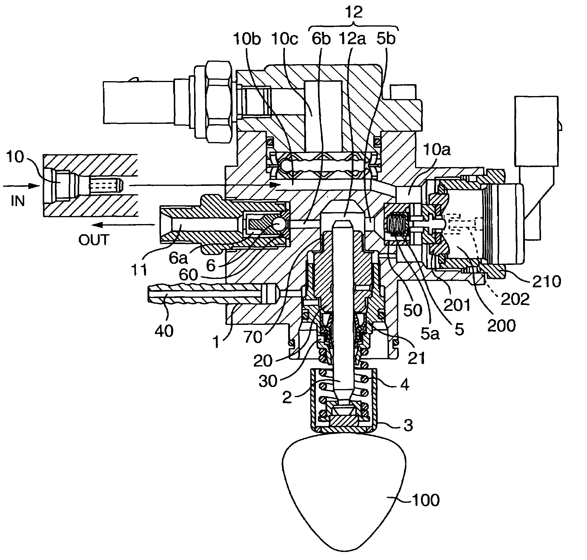
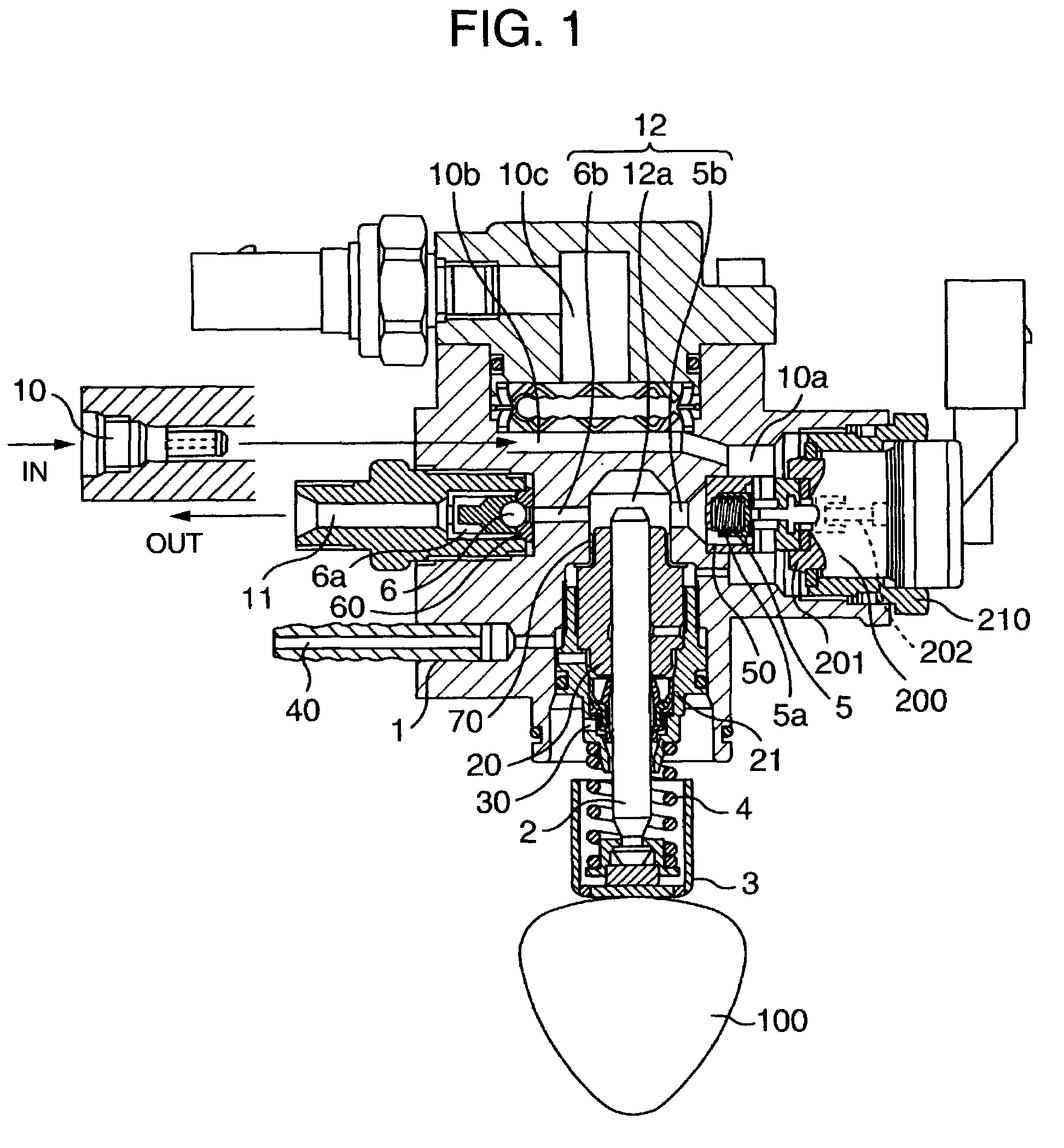
[0026]Referring to FIGS. 1 to 3, a basic configuration and operation of a high-pressure fuel pump according to an embodiment will be described. FIG. 1 is a vertical sectional view of an entire pump; FIG. 2 is an enlarged view of an interior of the pump in FIG. 1; and FIG. 3 shows a configuration of a fuel injection system.

[0027]A pump body 1 is formed with a fuel inlet passage 10, a discharge passage 11, and a pressurizing chamber 12. The inlet passage 10 and the discharge passage 11 are provided with an intake valve 5 and a discharge valve 6 respectively; each of which is held being urged in one direction by a spring 5a and a spring 6a respectively thereby acting as a check-valve to limit the direction of the fuel flow. The pressurizing chamber 12 is formed of a pump chamber 12 through which a pressurizing member, or a plunger 2 slides, an inlet 5b in communication with the intake valve 5, and an outlet 6b in communication with the discharge valve 6.

[0028]Further, in ...

embodiment 2

(Embodiment 2)

[0068]Next, another embodiment will be described referring to FIGS. 10, 11.

[0069]FIG. 10 shows a configuration in which the mechanism for reducing fuel pressure pulsation shown in FIG. 3 is placed in the low-pressure fuel passage upstream from the high-pressure fuel feed pump.

[0070]This configuration allows the low pressure pulsation of the fuel to be fed under pressure to the high-pressure fuel feed pump to be effectively reduced by means of a compact, low-cost damper, thereby making it possible to achieve a fuel feed system having a high-pressure fuel feed pump with the capability of stable discharge.

[0071]FIG. 11 shows a configuration in which the mechanism for reducing fuel pressure pulsation shown in FIG. 3 is placed in the high-pressure fuel passage downstream from the high-pressure fuel feed pump.

[0072]This configuration allows the pulsation of high-pressure fuel to be effectively reduced with a compact, low-cost damper, thereby making it possible to achieve a f...

embodiment 3

(Embodiment 3)

[0074]Now still another embodiment will be described. In FIG. 13, there is shown a fuel feed system for an internal combustion engine comprising a fuel tank 50 and a low-pressure pump 51 for feeding the fuel in the fuel tank to a fuel injection valve, wherein a mechanism 80 for reducing fuel pressure pulsation is provided and secured with a cover, and a fuel chamber is provided inside the cover.

[0075]This configuration allows the mechanism for reducing fuel pressure pulsation to be secured with a simple structure, making it possible to achieve a compact and low-cost fuel feed system.

[0076]According to the embodiment described so far, forming the above described diaphragm type damper for a fuel feed system of a metal allows the durability of the diaphragm to be enhanced, making it possible to achieve a fuel feed system composing of a damper having a wide range of working fuel pressure.

[0077]Also, in a fuel feed system for an internal combustion engine including a fuel t...


PUM


Abstract

A fuel feed system capable of feeding a fuel to fuel injection valves at a fuel pressure with improved stability is provided. A fuel feed system for an internal combustion engine including a fuel tank and a low-pressure pump for feeding the fuel in the fuel tank to fuel injection valves, is provided with a diaphragm type damper having a wave-shape cross section at a position in contact with the fuel. Also, in a high-pressure fuel feed pump including a pressurizing chamber for pressurizing the fuel, a plunger for pumping the fuel within the pressurizing chamber, an intake valve provided at a fuel inlet of the pressurizing chamber, a discharge valve provided at a fuel outlet of the pressurizing chamber, and a low-pressure chamber provided in an upstream of the intake valve, a mechanism for reducing fuel pressure pulsation is disposed in a space of the low-pressure chamber provided in the upstream of the intake valve, and a fuel pressure sensor for measuring the fuel pressure is mounted near the mechanism for reducing fuel pressure pulsation.

Description

BACKGROUND OF THE INVENTION[0001]The present invention relates to a fuel feed system for feeding fuel for fuel injection valves of an internal combustion engine.[0002]Regarding such a fuel feed system, mechanisms utilizing a single diaphragm to reduce fuel pressure pulsation are disclosed in JP-A-2001-55961, JP-A-2001-59466, JP-A-2000-297725, JP-A-2000-266183, JP-A-2000-265926, JP-A-2000-249019, JP-A-2000-193186, and Japanese patent No. 3180948.[0003]Moreover, methods utilizing a metal bellows as the mechanism to reduce fuel pressure pulsation are disclosed in JP-A-2001-82290 and JP-A-2001-59466.[0004]Furthermore, methods utilizing a rubber diaphragm as the mechanism to reduce fuel pressure pulsation are disclosed in JP-A-2001-65427 and JP-A-2000-265925.[0005]However, the inventors of the present invention have found that the above described prior embodiments have a following disadvantage. That is, when a single diaphragm is used as a mechanism to reduce fuel pressure pulsation, it ...

Claims


Application Information

Patent Timeline
IPC IPC(8): F02M37/04F02D33/00F02M37/00F02M55/00F02M55/02F02M55/04F02M59/36F02M59/44F02M63/00F02M63/02F04B11/00F04B49/24
CPCF02M55/04F02M59/366F02M59/44F02M63/0225F04B11/0016F04B49/243F02M37/0041F02D33/003F02M2200/247F02M37/0047F02M63/0001F02M2200/04F02M2200/24F02M2200/315F04B2205/01F04B2205/02F04B2205/05
Inventor USUI, SATOSHIODAKURA, HIROSHIONOSE, TORUSAITO, ATSUJIABE, MASAMIYAMADA, HIROYUKI
Owner HITACHI AUTOMATIVE SYST ENG
Why Eureka
Try Eureka