Bicycle power supply with discharge function

a technology of power supply and bicycle, applied in the field of bicycles, can solve the problems of sudden stop of electrical components, needing replacement, undesirable burden on the rider,

Inactive Publication Date: 2007-01-23
SHIMANO INC
View PDF21 Cites 35 Cited by
  • Summary
  • Abstract
  • Description
  • Claims
  • Application Information

AI Technical Summary

Problems solved by technology

However, batteries need to be replaced when their electricity is consumed, and such replacement places undesirable burdens on the rider.
Furthermore, the electrical components may suddenly stop operating when the batteries are depleted, which can be very problematic.
While the use of rechargeable batteries solves some of the problems of single-use batteries, they still h

Method used


Image

  • Bicycle power supply with discharge function
  • Bicycle power supply with discharge function
  • Bicycle power supply with discharge function

Examples


Embodiment Construction

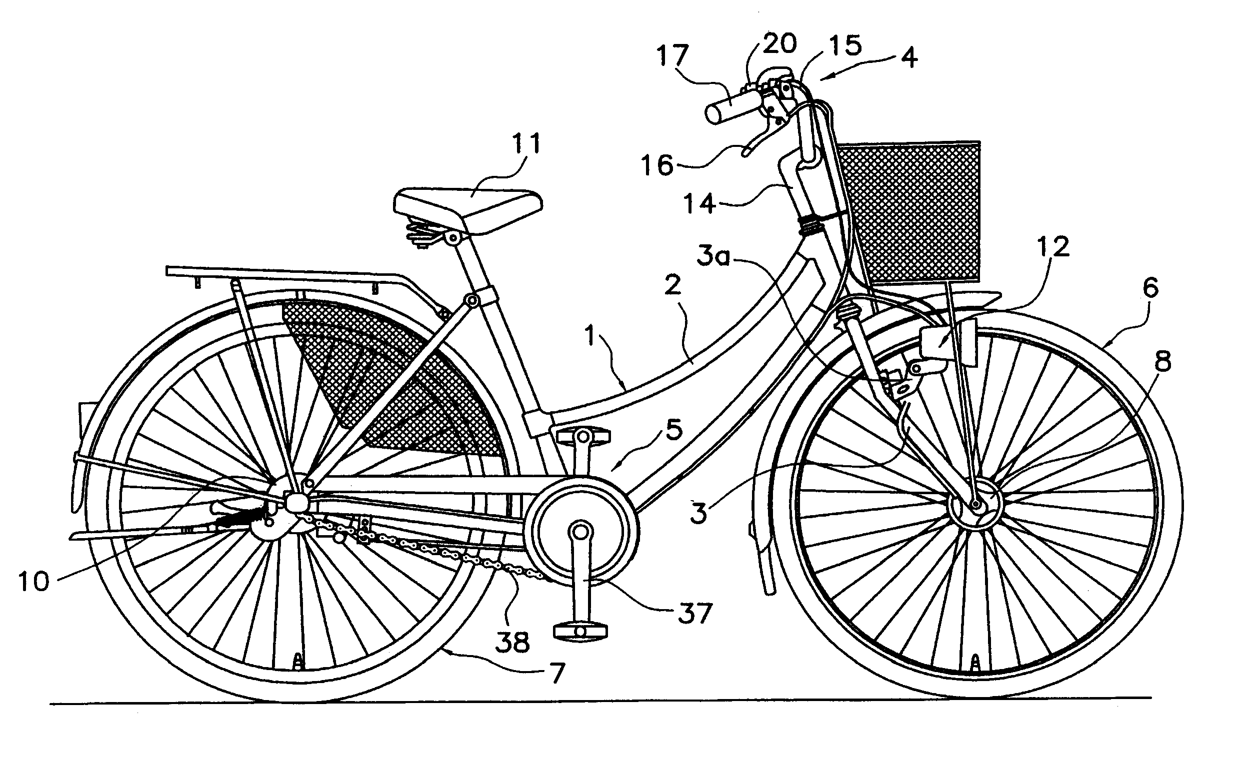
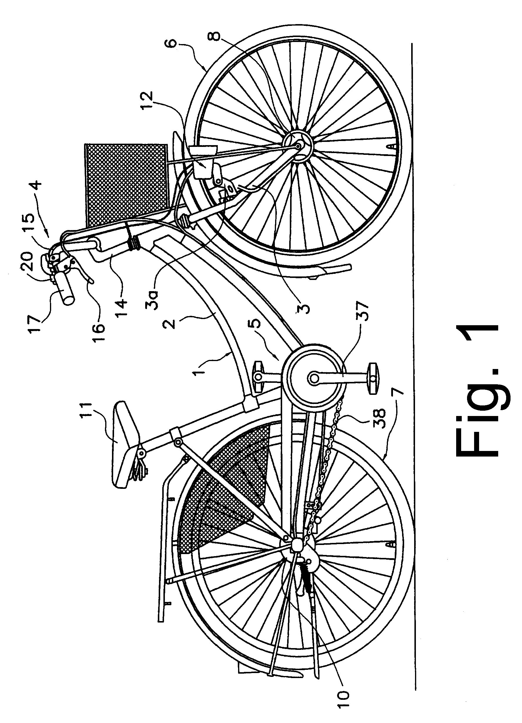
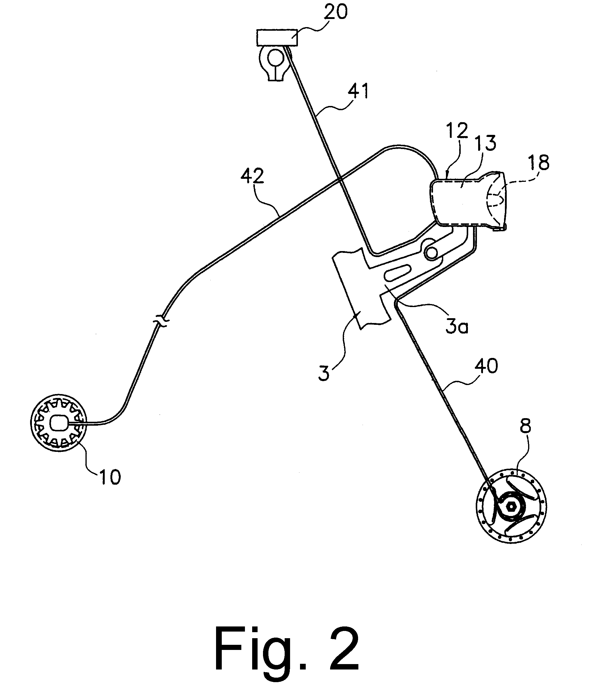
[0020]FIG. 1 is a side view of a bicycle 1 that includes a particular embodiment of a power supply. Bicycle 1 is a light roadster recreational bicycle comprising a double-loop frame body 2 formed from welded tubes, a front fork 3 mounted to the frame body 2 for rotation around an inclined axis, a handlebar assembly 4, a drive component 5, a front wheel 6 on which an alternating current generating dynamo hub 8 with brakes is mounted, a rear wheel 7 on which an internal shifting hub 10 is mounted, a saddle 11, a shift control unit 12 to control shifting of the internal shifting hub 10, and a shift controller 20 for manually operating the shift control unit 12.

[0021]The handlebar assembly 4 comprises a handle stem 14, fastened to the upper part of the front fork 3, and a handlebar 15 fastened to the handle stem 14. Brake levers 16 and grips 17 are mounted on both ends of the handlebar 15. In this embodiment, the shift controller 20 is integrated with the right-side brake lever 16. The ...


PUM


Abstract

A bicycle power supply apparatus comprises a battery unit; a bicycle condition detecting unit that detects when a bicycle is in a selected condition that ordinarily does not require drawing current from the battery unit for powering a current drawing element; and a current drawing unit that causes current to be drawn from the battery unit when the bicycle condition detecting unit detects the selected condition.

Description

BACKGROUND OF INVENTION[0001]The present invention is directed to bicycles and, more particularly, to a bicycle power supply with a discharge function.[0002]Some recent bicycles have been equipped with electronically controllable electrical components such as derailleurs, suspension devices, displays, etc., along with the electrical controllers for such components. A well-known example of this technology is an automatic bicycle transmission that uses a speed sensor to automatically change gears according to bicycle speed. In all cases, a power supply is required to supply electricity to the various electronic components. Sometimes batteries are used for such power supplies. However, batteries need to be replaced when their electricity is consumed, and such replacement places undesirable burdens on the rider. Furthermore, the electrical components may suddenly stop operating when the batteries are depleted, which can be very problematic.[0003]To avoid the above problems, some systems...

Claims


Application Information

Patent Timeline
IPC IPC(8): B62M23/02B62J6/02B62J6/00B62J6/16B62J99/00H02J7/00H02J7/14H02J7/34H02M7/06
CPCB60L1/16B60L11/007B60L11/1861B60L11/1872B62J6/003B62J6/06B62M6/90B62M25/08H02J7/1407B60L11/1859B60L2200/12B60L2210/20B60L2250/16Y02T10/7005Y02T10/7044Y02T10/705Y02T10/725B60L50/20B60L58/25B62J6/015Y02T10/70Y02T10/72
Inventor KITAMURA, SATOSHI
Owner SHIMANO INC
Why Eureka
Try Eureka