

Ventilation member and vented housing using the same
a technology of ventilation member and venting housing, which is applied in the direction of gas-tight/water-tight arrangements, coupling device connections, combination devices, etc., can solve the problem and achieve the effect of reducing the possibility of ventilation member being pulled out of the housing
- Summary
- Abstract
- Description
- Claims
- Application Information
AI Technical Summary
Benefits of technology
Problems solved by technology
Method used
Image

Examples
embodiment 1
[0031]Description will be made about an embodiment of a ventilation member according to the invention with reference to FIGS. 1, 2A, 2B, 3, 4A, 4B, 5A to 5G, 6A to 6F, 7A, and 7B.
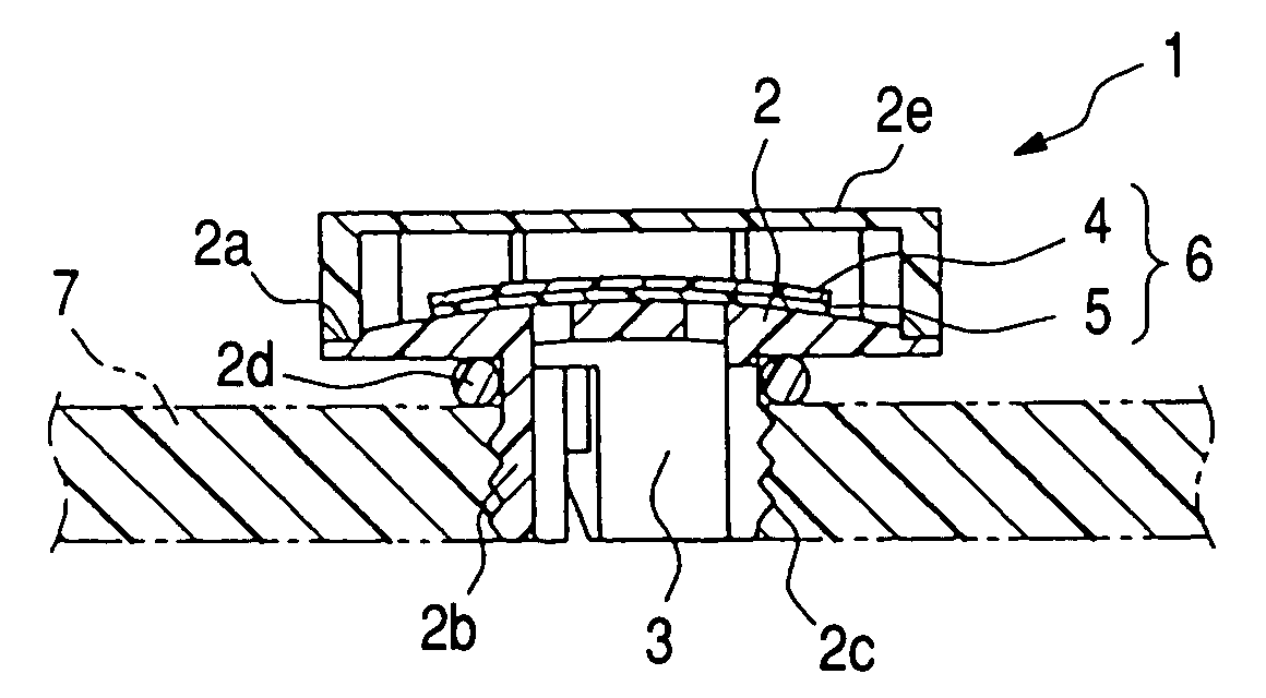
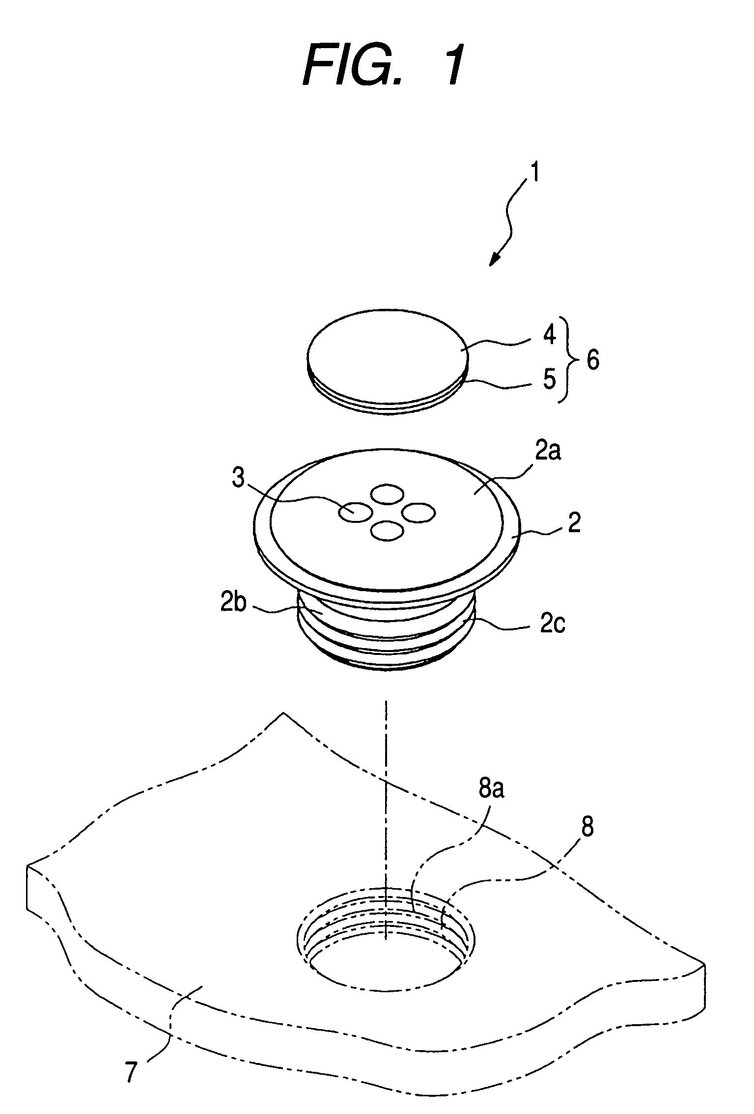
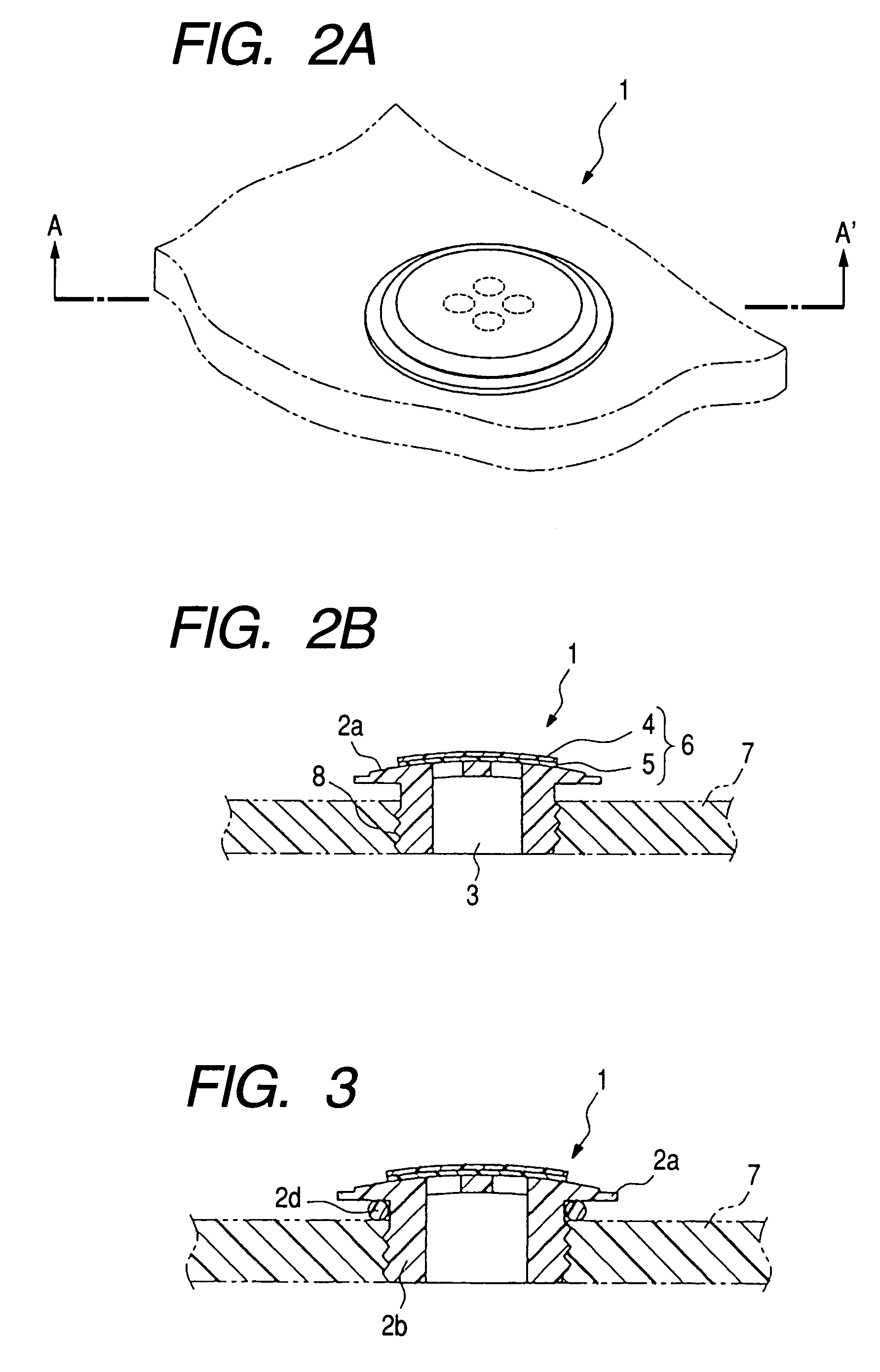
[0032]A ventilation member 1 shown in FIGS. 1, 2A and 2B is a ventilation member including a breathable film 4. The breathable film 4 transmits gas passing through an opening portion 8 of a housing 7 when the breathable film 4 is fixed to the opening portion 8. The ventilation member 1 further includes a support 2. The support 2 includes a supporting portion 2a for supporting the breathable film 4, and an insertion portion 2b to be inserted into the opening portion 8 of the housing 7. A spiral groove 2c is formed in the outer circumference of the insertion portion 2b. By screwing the insertion portion 2b down to a female screw 8a formed in the opening portion 8 of the housing 7, the ventilation member 1 can be fixed to the opening portion 8 of the housing 7. Thus, the possibility that the ventilation member...
embodiment 2
[0056]Another embodiment of a ventilation member according to the invention will be described with reference to FIGS. 7A and 7B and FIGS. 8A to 8C.
[0057]A ventilation member 21 shown in FIGS. 7A and 7B is a ventilation member including a breathable film 4. The breathable film 4 transmits gas passing through an opening portion 8 of a housing 7 when the breathable film 4 is fixed to the opening portion 8. The ventilation member 21 further includes a support 2. The support 2 includes a supporting portion 2a for supporting the breathable film 4, and an insertion portion 2b to be inserted into the opening portion 8 of the housing 7. At least one protrusion portion 2p is formed in the outer circumference of the insertion-start-side end portion of the insertion portion 2b.
[0058]The insertion portion 2b has a columnar shape whose diameter is substantially the same as that of the opening portion 8 of the housing 7 in the embodiment shown in FIGS. 7A and 7B. Four protrusion portions 2p are f...
example 1
[0063]As Example 1, the ventilation member 1 shown in FIGS. 4A and 4B was produced as follows.
[0064]First, the support 2 having a structure shown in FIGS. 4A and 4B was obtained by injection molding out of PBT (CG7640 made by Teijin Ltd., melting point 225° C.). The supporting portion 2a of the obtained support was 2.5 mm in thickness and 16 mm in outer diameter, the insertion portion 2b of the obtained support was 12 mm in outer diameter, and the through holes 3 provided in the insertion portion 2b were 8 mm in inner diameter.
[0065]Next, a PTFE porous material (Microtex NTF1131 made by Nitto Denko Corp., melting point 327° C.) 0.085 mm in thickness and 20 mm in outer diameter was prepared as the breathable film 4, and polyester-based nonwoven fabric (Axtar made by Toray Industries, Inc., melting point 230° C.) 0.2 mm in thickness was prepared as the reinforcement material 5. The breathable film 4 and the reinforcement material 5 were contact-bonded by heating deposition at a temper...
PUM
| Property | Measurement | Unit |
|---|---|---|
| Force | aaaaa | aaaaa |
| Force | aaaaa | aaaaa |
| Shape | aaaaa | aaaaa |
Abstract
Description
Claims
Application Information