
Digital broadcasting receiver and method for compensating color reproduction error of the same

a digital broadcasting receiver and color reproduction technology, applied in the direction of color television with bandwidth reduction, synchronisation signal speed/phase control, television systems, etc., can solve the problem of color demodulation error, and achieve the effect of stable provision of composite pictures

Inactive Publication Date: 2007-01-23
LG ELECTRONICS INC
View PDF3 Cites 2 Cited by
  • Summary
  • Abstract
  • Description
  • Claims
  • Application Information

AI Technical Summary

Benefits of technology

[0020]An object of the present invention is to provide a digital broadcasting receiver which can assure stable provision of a composite picture.
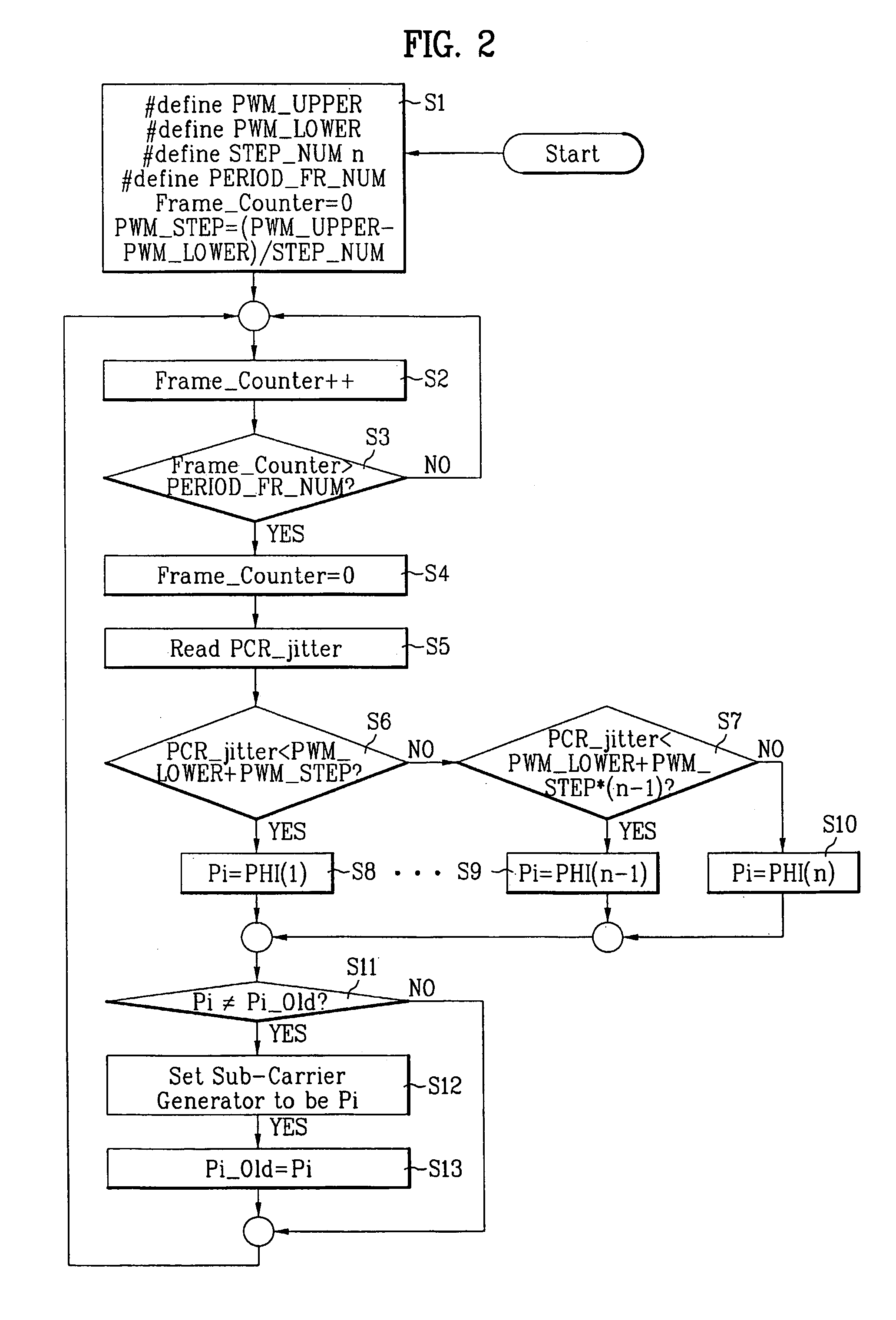
[0021]Another object of the present invention is to provide a method for a color reproduction error in a digital broadcasting receiver, which can compensate a picture signal for a color reproduction error caused by a system clock variation.

Problems solved by technology

In this case, if the sub-carrier frequency is not compensated, it is liable that a color demodulation error can be occurred at an analog receiver which receives a composite picture signal from a digital broadcasting receiver.

Method used


Image

  • Digital broadcasting receiver and method for compensating color reproduction error of the same
  • Digital broadcasting receiver and method for compensating color reproduction error of the same
  • Digital broadcasting receiver and method for compensating color reproduction error of the same

Examples


Embodiment Construction

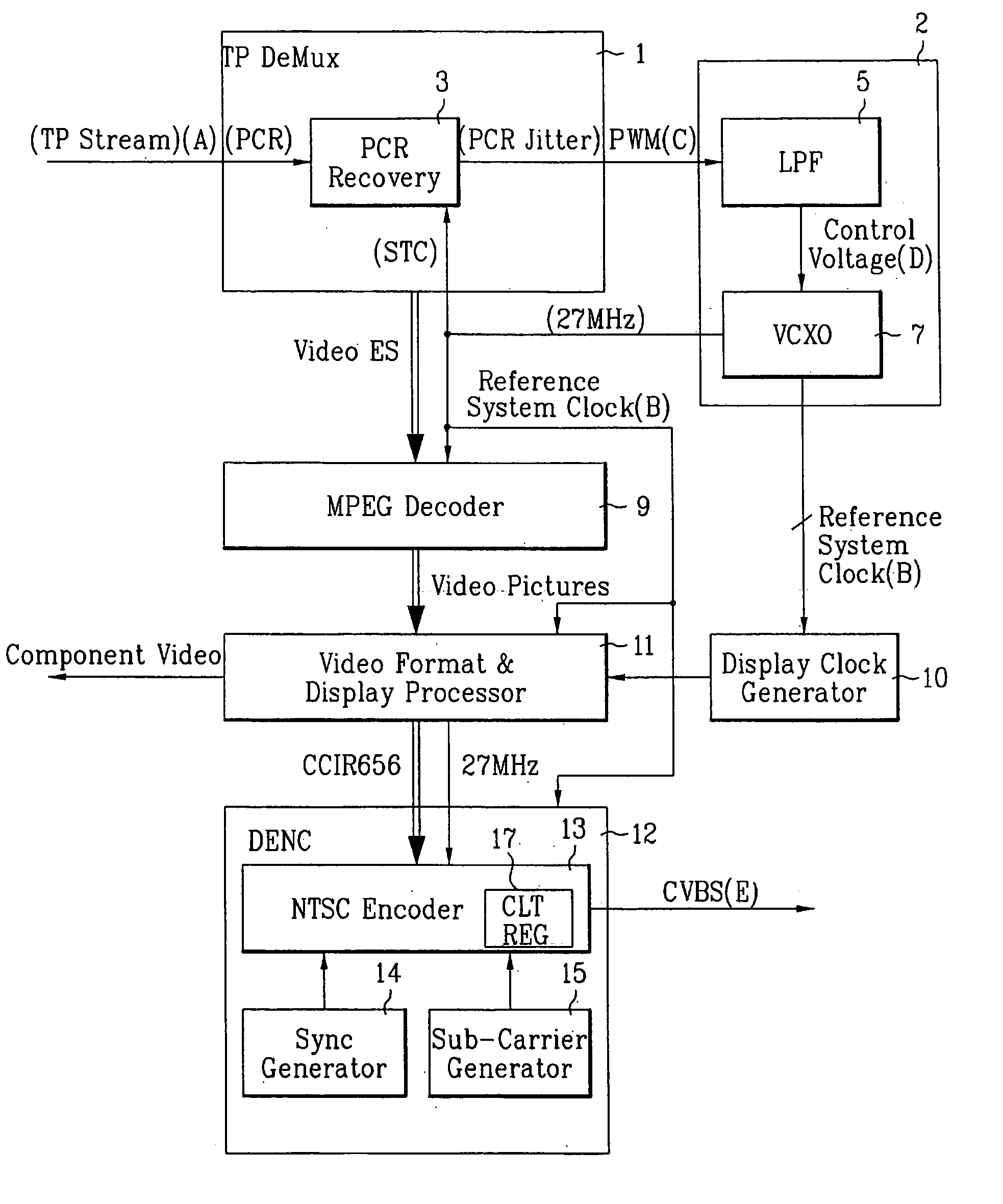
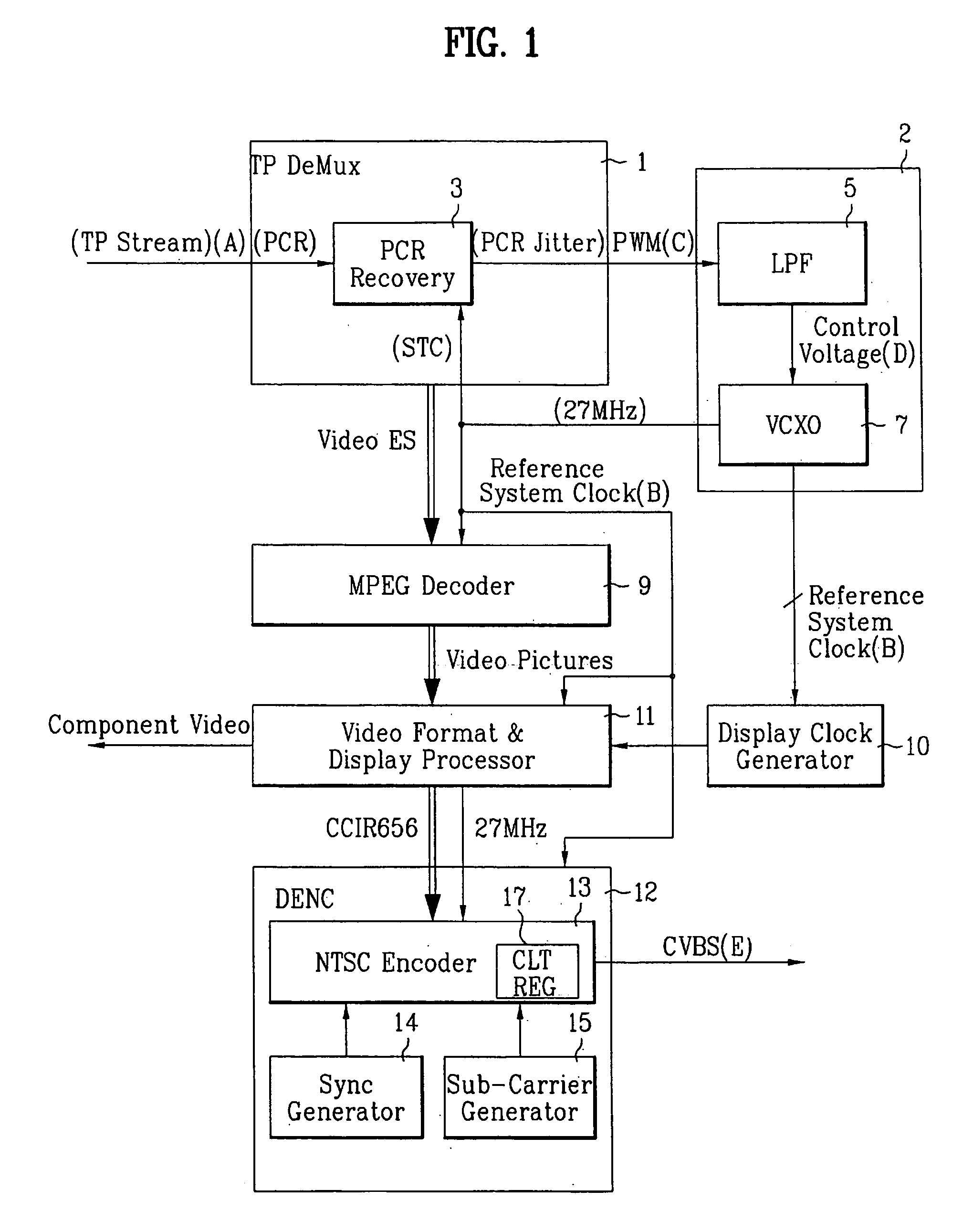
[0036]Reference will now be made in detail to the preferred embodiments of the present invention, examples of which are illustrated in the accompanying drawings. FIG. 1 illustrates a block diagram of a digital broadcasting receiver operative under single system clock in accordance with a preferred embodiment of the present invention.

[0037]Referring to FIG. 1, the digital broadcasting receiver includes a channel decoder (not shown), a TP (transport) part 1, an STC (system time clock) compensating part 2, a decoder 9, a display clock generator 10, a video format and display processor 11, and an analog composite picture signal generating part 12.

[0038]A system and operation of the digital broadcasting receiver will be described with reference to FIG. 1.

[0039]The TP part 1 demultiplexes a TP stream ‘A’, which is a result of channel decoding at the channel decoder, to obtain a PCR, receives an STC, and provides a PCR jitter which is a difference between the PCR and the STC. That is, the ...


PUM


Abstract

Digital broadcasting receiver, and method for compensating a color reproduction error therein, the digital broadcasting receiver including a channel decoder, a TP part for demultiplexing a TP stream from the channel decoder for being provided with a PCR (Program Clock Reference), and receiving a receiver side STC (System Time Clock), and providing a PCR jitter which is a difference between the PCR and an STC value, an STC compensating part for providing the STC value to the TP part from a system clock, and varying the system clock so that the PCR value and the STC value are identical, to generate a reference system clock in which the PCR jitter value becomes ‘0’, a decoder for receiving the reference system clock from the STC compensating part, and decoding a received picture, a display clock generator for providing a display clock generated by receiving the reference system clock as singular system clock, a video format and display processor for receiving the reference system clock and the display clock, and carrying out format conversion and display processing, and an analog composite picture signal generating part for compensating a sub-carrier frequency value from a reference system clock value, and encoding the received picture to provide a composite picture signal.

Description

[0001]This application claims the benefit of the Korean Application No. P2002-9944 filed on Feb. 25, 2002, which is hereby incorporated by reference.BACKGROUND OF THE INVENTION[0002]1. Field of the Invention[0003]The present invention relates to a digital broadcasting receiver, and a method for compensating a color reproduction error therein, in which a color reproduction error of a picture signal is minimized when there is a system clock variation with reference to a Program Clock Reference (PCR).[0004]2. Background of the Related Art[0005]Following the ceaseless effort for putting digital broadcasting technologies into practical use for recent several years, an air borne digital television (DTV) broadcasting wave reaches even to living rooms, and receivers are supplied, partly. Starting from unitary models, there are a variety of models of the digital broadcasting receivers, such as separable set-top model.[0006]Though there may be countless development, such as channel coding sys...

Claims


Application Information

Patent Timeline
IPC IPC(8): H04N7/01H04N11/02H04L7/04H04N9/77H04N5/00H04N5/44H04N9/45
CPCH04N9/45H04N21/4402H04N21/4305H04N21/4302H04N5/4401H04N21/426H04N9/77
Inventor PARK, DONG HO
Owner LG ELECTRONICS INC
Learn More