Exact volume imaging involving multiple partial scans

a technology of exact volume and partial scans, applied in the field of xray imaging systems, can solve the problems of impracticality of achieving the above-complete source trajectory with the current c-arm imaging system

Inactive Publication Date: 2007-01-23
SIEMENS HEALTHCARE GMBH
View PDF13 Cites 7 Cited by
  • Summary
  • Abstract
  • Description
  • Claims
  • Application Information

AI Technical Summary

Problems solved by technology

However the volume outside the mid-plan only provides enough information for an approximate reconstruction.
However, the above complete source trajectories are impractical to achieve with the current C-arm imaging systems.

Method used


Image

  • Exact volume imaging involving multiple partial scans
  • Exact volume imaging involving multiple partial scans
  • Exact volume imaging involving multiple partial scans

Examples


Embodiment Construction

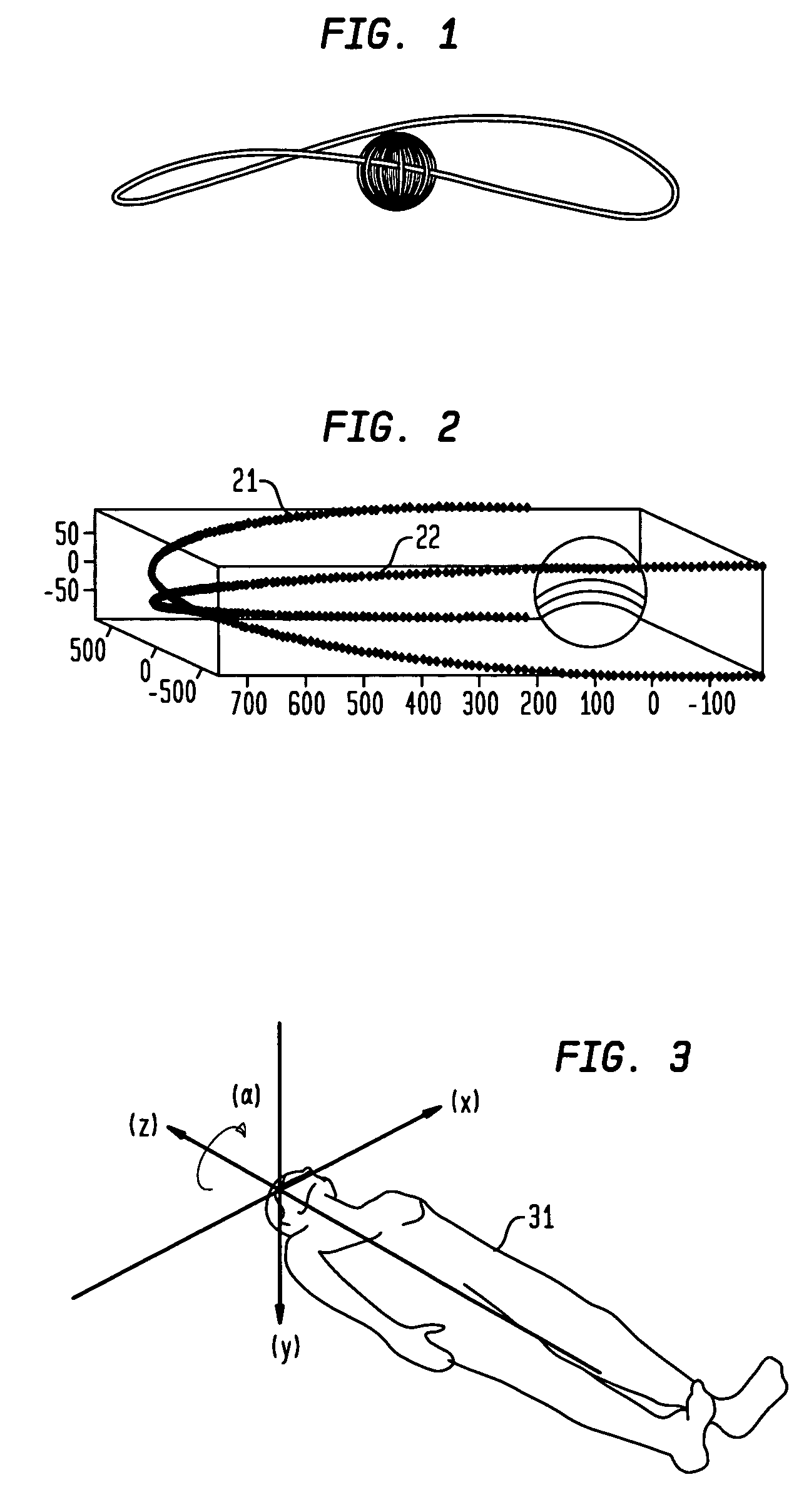
[0017]According to the present invention, a method for providing a complete source trajectory to achieve an exact reconstruction of a scan field of view is provided. See FIG. 2. In essence, a first partial circle scan is used for source trajectory 21, and then the plane of the C-arm is rotated at an angle to the z-axis. Then a second partial circle scan 22 is performed. Together these constitute a complete source trajectory. Such a complete source trajectory can be completed with current C-arm systems and at constitute source speed. The angle between the planes defined by the two partial (or short) circle scans is β. The angle of the cone from the source to encompass a volume r within or partially within the patient is the the angle βcone. According to the present invention, β=βcone.

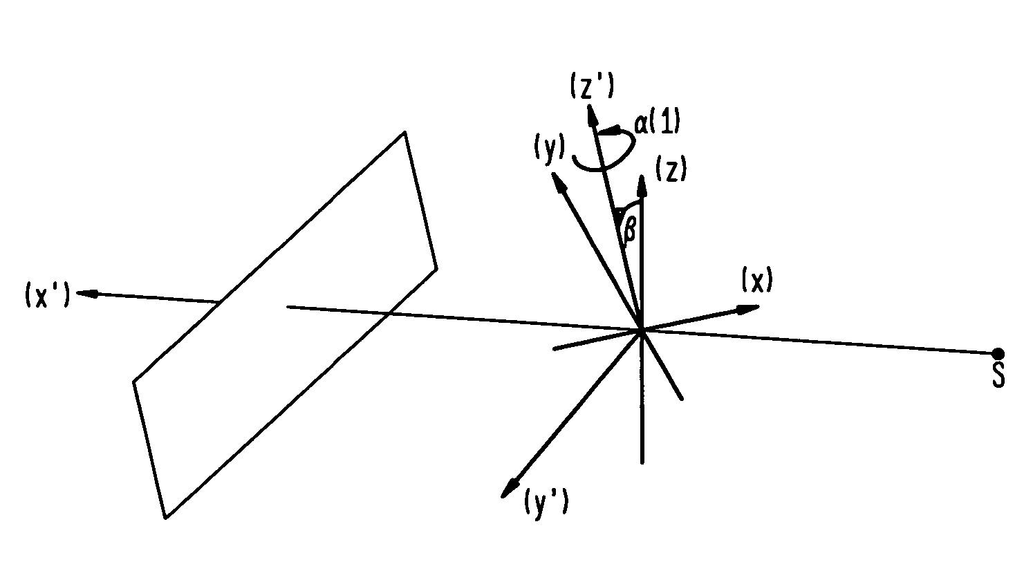
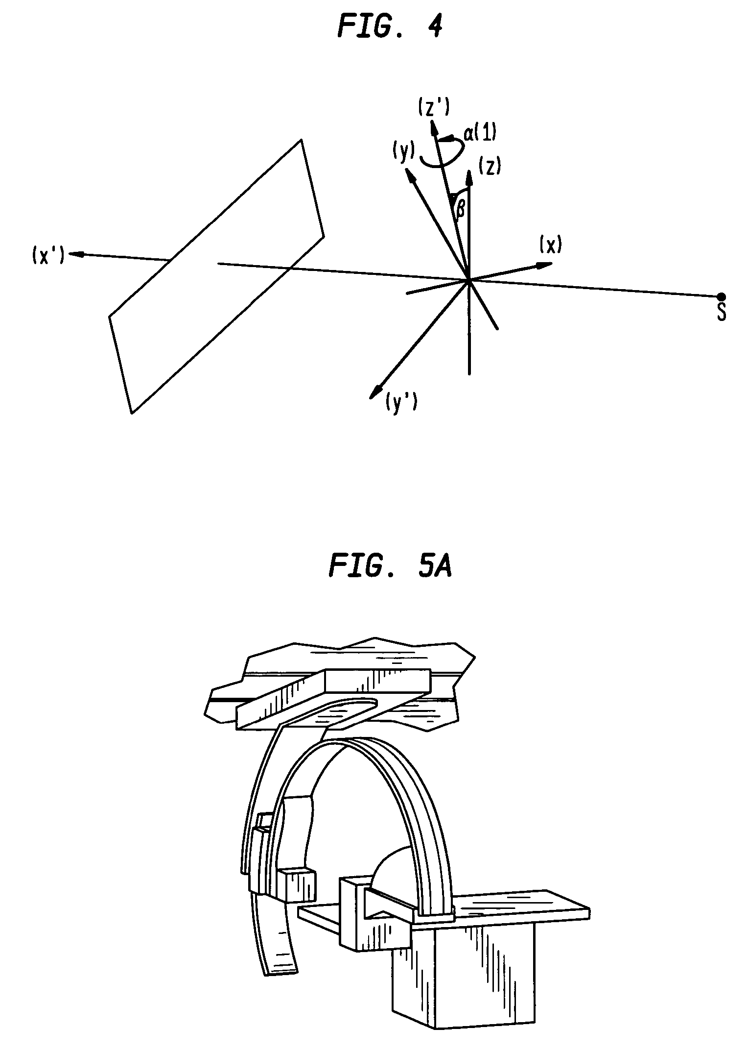
[0018]FIG. 3 defines the x,y,z coordinates and the β angle with respect to a patient body 31. FIG. 4 defines the angle β. where the z,y,z and x′,y′,z′ represent the two coordinate systems created by the ...


PUM


Abstract

A method for performing an exact volume imaging with a C-arm digital x-ray imaging system by moving the source through two partial circular scans which form a complete source trajectory. The partial circular scans form a complete source trajectory when the plane defined by the C-arm is repositioned for the second scan at an angle equal to the cone angle with respect to the long axis of the patient.

Description

PRIORITY CLAIM[0001]This application claims priority under 35 U.S.C. 120 to Provisional Application No. 60 / 557,475 filed on Mar. 30, 2004, entitled “Volume Imaging Involving Multiple Partial Scans”, which is hereby incorporated by reference in its entirety.BACKGROUND OF THE INVENTION[0002]1. Field of the Invention[0003]This invention relates generally to x-ray imaging systems with a C-arm which can be used for volume imaging. More specifically, this invention relates to scanning methods and algorithms used for volume reconstruction.[0004]2. Background and Prior Art[0005]Digital x-ray systems include C-arm volume imaging systems. These C-arm imaging systems have a source and detector that are 180 degrees opposite of each other at the ends of a C-arm. The C-arm itself is capable of being translated along the axis of the patient (the z-axis) (or the patient table can be translated) and capable of being rotated about that axis. The x-ray sources of these C-arm imaging systems can be mod...

Claims


Application Information

Patent Timeline
Patent Type & Authority Patents(United States)
IPC IPC(8): A61B6/03A61B6/00
CPCA61B6/027A61B6/4441A61B6/4447
Inventor STROBEL, NORBERT KARLRAMAMURTHI, KRISHNAKUMAR
Owner SIEMENS HEALTHCARE GMBH
Why Eureka
Try Eureka