Systems and methods for adaptive volume imaging

a volume imaging and volume rate technology, applied in the field of volume imaging, can solve the problems of not always providing practitioners with a desired view of the target, difficult or very difficult to identify particular structures of interest, and difficult to use traditional 2d ultrasound imaging techniques, etc., to achieve the effect of improving volume rate and image quality

Active Publication Date: 2013-01-15
FUJIFILM SONOSITE
View PDF35 Cites 27 Cited by
  • Summary
  • Abstract
  • Description
  • Claims
  • Application Information

AI Technical Summary

Benefits of technology

[0008]The present invention is directed to systems and methods which provide volume imaging by implementing survey and target imaging modes. According to embodiments of the invention, a survey imaging mode is implemented to provide a volume image of a relatively large survey area. An area, point, or item (collectively referred to as a target) of interest is preferably identified within the survey area for use in a target imaging mode. Embodiments of the invention implement a target imaging mode to provide a volume image of a relatively small target area corresponding to the identified target of interest. The target imaging mode preferably adapts the beamforming, volume field of view, and / or other signal and image processing algorithms to the target area. In operation according to embodiments of the invention, the target imaging mode provides a volume image of a target area with improved volume rate and image quality.

Problems solved by technology

However, the planar, vertical “slice” views typically provided by such 2D ultrasound imaging has not always provided practitioners with a desired view of the target.
For example, particular structure of interest is often difficult to identify from a planar slice through that structure.
Often, a view of a surface of a target structure is desired, which is often impossible or very difficult using traditional 2D ultrasound imaging techniques.
A disadvantage of volume imaging is its much slower volume rate compared to 2D imaging frame rates.
Moreover, volume imaging techniques often suffer from degraded image quality for any arbitrary plane, especially the elevation plane if the volume is obtained by a wobbler transducer.
For example, image quality is often limited, when a wobbler transducer is used, by a single-element beam providing poor sampling of the elevation plane and, when a matrix array transducer is used, by the limited number of elements of the matrix array (e.g., 32 to 64 compared to 128 to 256 elements for standard array transducer) and sparse beams in 3D space.

Method used


Image

  • Systems and methods for adaptive volume imaging
  • Systems and methods for adaptive volume imaging
  • Systems and methods for adaptive volume imaging

Examples


Embodiment Construction

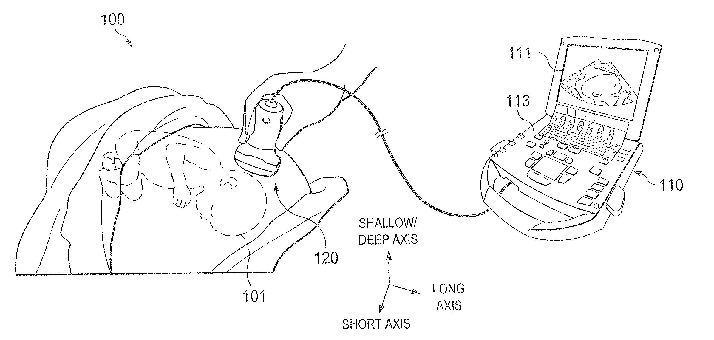
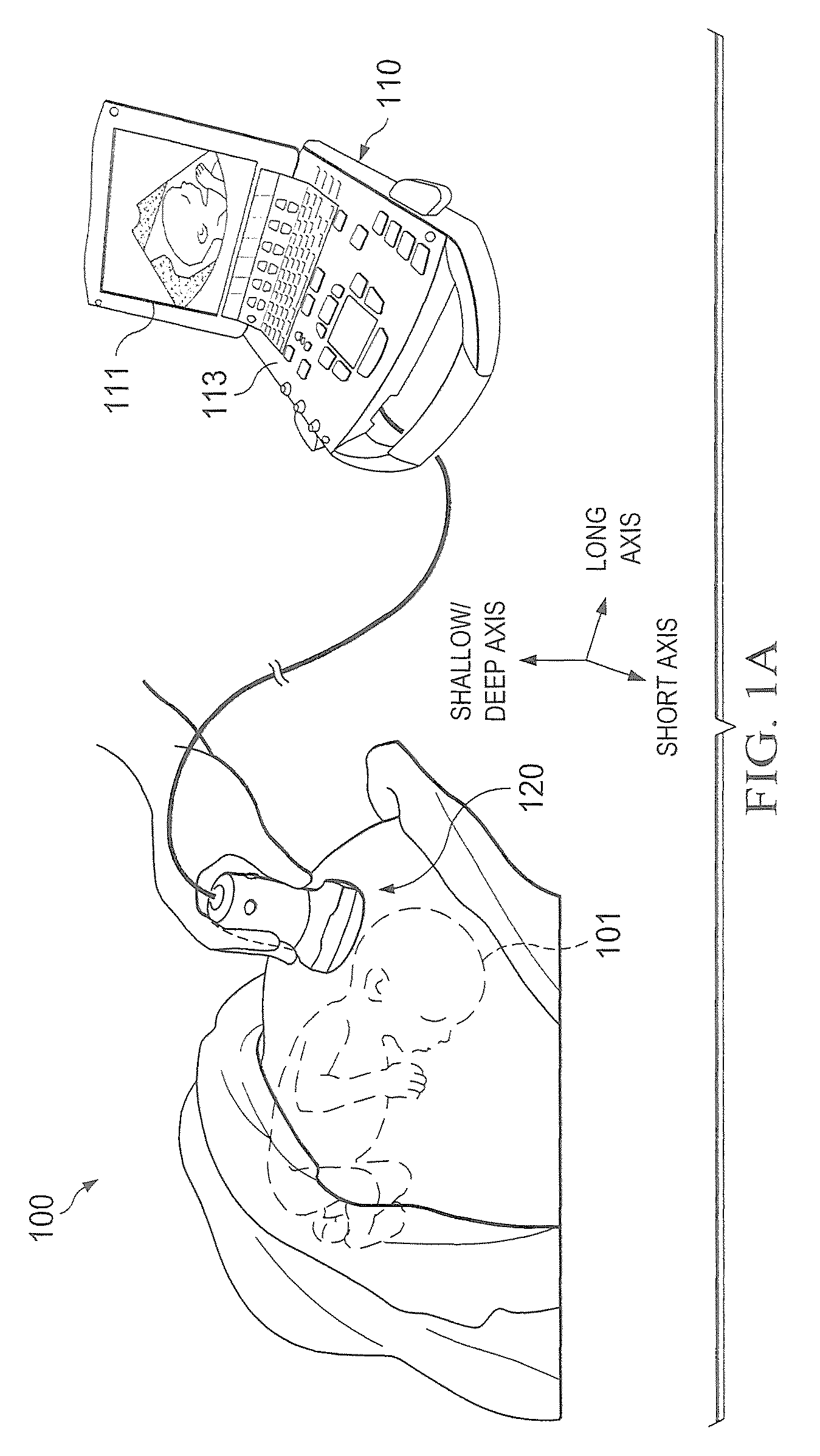
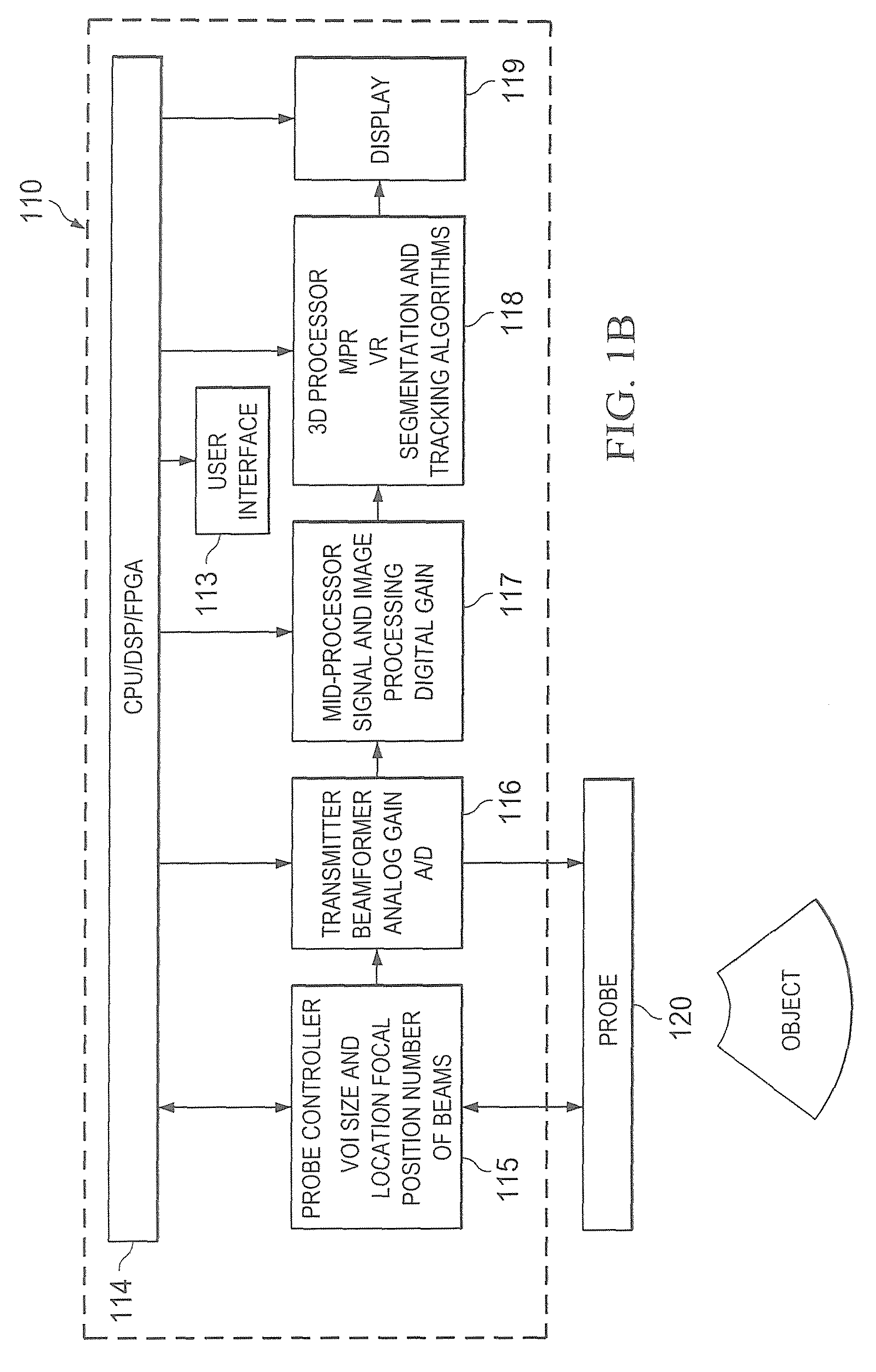
[0016]Directing attention to FIG. 1, a system adapted according to embodiments of the invention is shown as system 100. System 100 may, for example, comprise a diagnostic ultrasound system operable to provide 2D and / or 3D images from a multi-dimensional (e.g. 3D and / or 4D) volume dataset. Although embodiments of the invention are described herein with reference to ultrasound imaging technology, in order to aid the reader in understanding the invention, it should be appreciated that the concepts of the present invention are not limited in applicability to ultrasound imaging. For example, embodiments of the present invention may be implemented with respect to fluoroscope systems, X-ray imaging systems, ultrasound imaging systems, CT imaging systems, MRI systems, positron emission tomography (PET) imaging systems, and the like.

[0017]System 100 of the illustrated embodiment includes system unit 110 and transducer 120 coupled thereto. System unit 110 preferably comprises a processor-base...


PUM


Abstract

Systems and methods which provide volume imaging by implementing survey and target imaging modes are shown. According to embodiments, a survey imaging mode is implemented to provide a volume image of a relatively large survey area. A target of interest is preferably identified within the survey area for use in a target imaging mode. Embodiments implement a target imaging mode to provide a volume image of a relatively small target area corresponding to the identified target of interest. The target imaging mode preferably adapts the beamforming, volume field of view, and / or other signal and image processing algorithms to the target area. In operation according to embodiments, the target imaging mode provides a volume image of a target area with improved volume rate and image quality.

Description

CROSS-REFERENCE TO RELATED APPLICATIONS[0001]The present application is related to co-pending and commonly assigned U.S. patent application Ser. No. 12 / 269,623 entitled “Systems and Methods for Image Presentation for Medical Examination and Interventional Procedures,” filed Nov. 12, 2008, and Ser. No. 12 / 269,663 entitled “Systems and Methods to Identify Interventional Instruments,” filed Nov. 12, 2008, the disclosures of which are hereby incorporated herein by reference.TECHNICAL FIELD[0002]The invention relates generally to volume imaging and, more particularly, to providing adaptive volume imaging.BACKGROUND OF THE INVENTION[0003]Various forms of imaging apparatus have been used extensively for medical applications. For example, fluoroscope systems, X-ray imaging systems, ultrasound imaging systems, computed tomography (CT) imaging systems, and magnetic resonance (MR) imaging (MRI) systems have been used for a number of years. Any number of medical examination, interventional proc...

Claims


Application Information

Patent Timeline
Patent Type & Authority Patents(United States)
IPC IPC(8): G06K9/00
CPCA61B6/469A61B6/488A61B8/08A61B8/0866A61B8/483A61B8/54G06K9/3241G06T7/0012A61B8/469A61B8/0891A61B5/0037G06K2209/05G06V10/255G06V2201/03
Inventor MA, QINGLINPAGOULATOS, NIKOLAOS
Owner FUJIFILM SONOSITE
Why Eureka
Try Eureka