Thermal sensing detector cell for a computed tomography system and method of manufacturing same

a computed tomography and detector cell technology, applied in the field of computed tomography imaging, can solve the problems of reducing the overall detector cell size and spatial resolution of the detector, limiting the ability to reduce the overall detector cell size and spatial resolution, and reducing the diagnostic image of poor quality or lower sensitivity, so as to achieve improved diagnostic image quality and sensitivity. the effect of improving

Inactive Publication Date: 2007-01-23
GENERAL ELECTRIC CO
View PDF17 Cites 49 Cited by
  • Summary
  • Abstract
  • Description
  • Claims
  • Application Information

AI Technical Summary

Benefits of technology

[0007]It would therefore be desirable to design a detector cell for sensing thermal differentials in the detector cell resulting from the absorption of HF electromagnetic energy thereby providing improved, higher resolution, and more sensitive detector signal output to a data processing system of a CT system.

Problems solved by technology

The minimum requirements yield higher costs as well as limit the ability to reduce the overall detector cell size and spatial resolution of the detector.
Furthermore, detection inefficiencies in this two step detection process, x-rays to light and light to electrical signals, has efficiency losses resulting in a diagnostic image of poorer quality or lower sensitivity.

Method used


Image

  • Thermal sensing detector cell for a computed tomography system and method of manufacturing same
  • Thermal sensing detector cell for a computed tomography system and method of manufacturing same
  • Thermal sensing detector cell for a computed tomography system and method of manufacturing same

Examples


Embodiment Construction

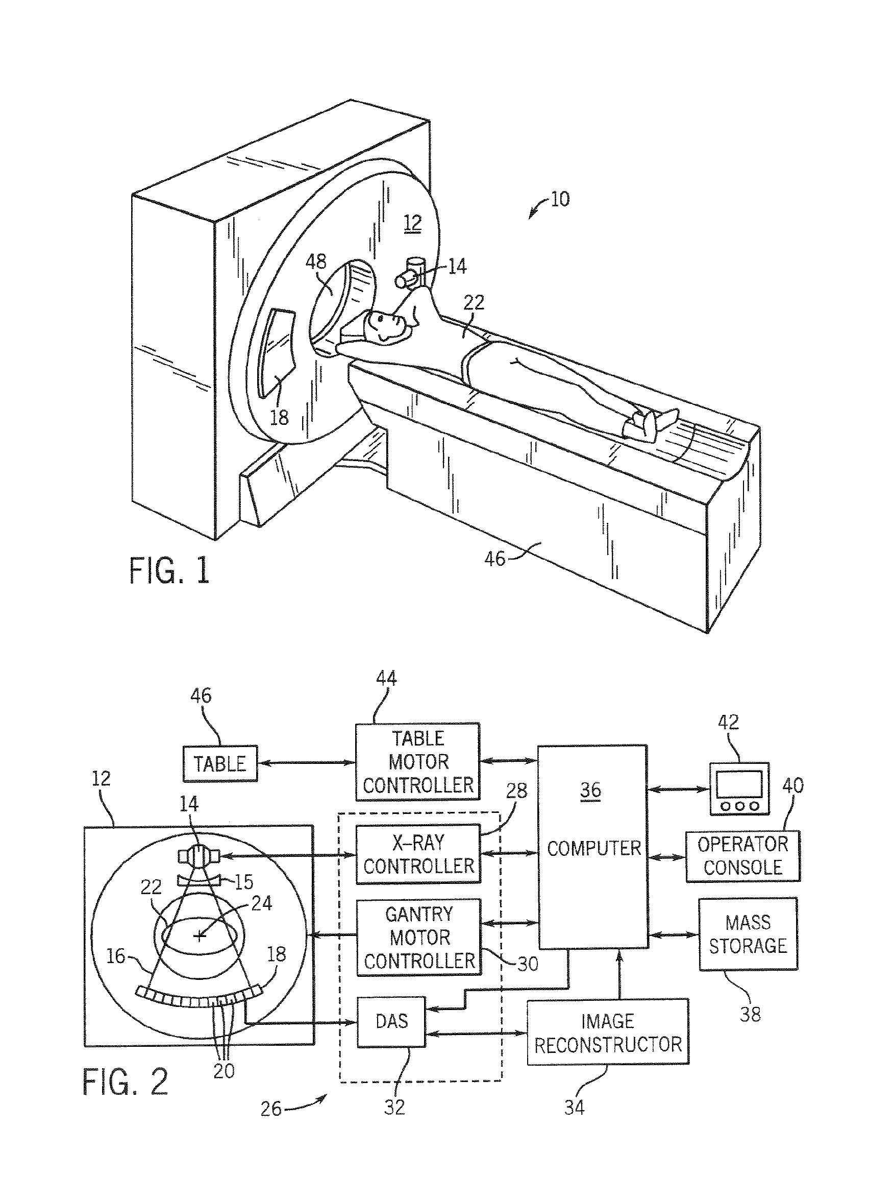
[0022]The operating environment of the present invention is described with respect to a four-slice computed tomography (CT) system. However, it will be appreciated by those skilled in the art of CT that the present invention is equally applicable for use with single-slice or other multi-slice configurations. Moreover, the present invention will be described with respect to the detection and conversion of x-rays. However, one skilled in the art will further appreciate that the present invention is equally applicable for the detection and conversion of other HF electromagnetic energy. Further, the present invention will be described with respect to a “third generation” CT system. However, the present invention is also applicable with first, second, and fourth generation CT systems.

[0023]Referring to FIGS. 1 and 2, a computed tomography (CT) imaging system 10 is shown as including a gantry 12 representative of a “third generation” CT scanner. Gantry 12 has an x-ray source 14 that proje...


PUM


Abstract

The present invention provides a method of manufacturing a CT detector cell having an x-ray absorption component and a thermal sensing component. The thermal sensing component is configured to detect thermal differentials in the absorption component resulting from the absorption of x-rays.

Description

CROSS REFERENCE TO RELATED APPLICATIONS[0001]The present application is a divisional and claims priority of U.S. Ser. No. 09 / 683,869 filed Feb. 25, 2002 now U.S. Pat. No. 6,654,443.BACKGROUND OF INVENTION[0002]The present invention relates generally to computed tomography imaging and, more particularly, to a detector cell for sensing thermal changes in response to the absorption of HF electromagnetic energy for use with computed tomography systems.[0003]Typically, in computed tomography (CT) imaging systems, an x-ray source emits a fan-shaped beam towards a subject or object, such as a patient or a piece of luggage. Hereinafter the terms “subject” and “object” shall include anything capable of being imaged. The beam, after being attenuated by the subject, impinges upon an array of radiation detectors. The intensity of the attenuated beam radiation received at the detector array is typically dependent upon the attenuation of the x-ray beam by the subject. Each detector element of the...

Claims


Application Information

Patent Timeline
Patent Type & Authority Patents(United States)
IPC IPC(8): A61B6/00G01T1/29G01V5/00G06K9/00
CPCG01V5/005G01T1/2985
Inventor HOFFMAN, DAVID M.
Owner GENERAL ELECTRIC CO
Why Eureka
Try Eureka