Method and devices of measuring physical quantities

a physical quantity and measurement method technology, applied in the direction of turning-sensitive devices, acceleration measurement using interia forces, instruments, etc., can solve the problems of noise in the detection signal, alignment error between the photo masks, and vibration deviating among the vibrators, so as to reduce noise and temperature drift

Inactive Publication Date: 2007-01-30
SEIKO EPSON CORP
View PDF13 Cites 10 Cited by
  • Summary
  • Abstract
  • Description
  • Claims
  • Application Information

AI Technical Summary

Benefits of technology

[0011]An object of the present invention is to reduce a noise and temperature drift due to unbalance of the shape of a vibrator actually produced, when the vibrator is used for measuring a physical quantity.
[0015]According to the present invention, when a driving vibration is excited in a vibrator, output signals are output from the detecting means based on a detection vibration excited in the vibrator responsive to the physical quantity. The weight of each of the films is adjusted based on a comparison of the output signals from the detection vibration arms. After the adjustment, the ratio of the weights of the driving vibration arms is changed, so that the pattern and mode of the driving vibration are slightly changed as well as those of the detection vibration. It is thus possible to adjust the weights of the films so that the noises in the output signal drawn from the detecting means are reduced.

Problems solved by technology

When the zero point temperature drift is measured for each of the vibrators actually fabricated, however, the drift may deviate among the vibrators.
When the photo masks are mounted on both of the upper and lower faces of the wafer and aligned with each other, alignment error may occur between the photo masks.
Such kind of the unnecessary vibration component in Z-axis is induced in a bending vibration arm for detection at the same time to result in a noise in the detecting signal.
According to the method, however, the design of the thickness of the wafer is considerably limited.

Method used


Image

  • Method and devices of measuring physical quantities
  • Method and devices of measuring physical quantities
  • Method and devices of measuring physical quantities

Examples


Embodiment Construction

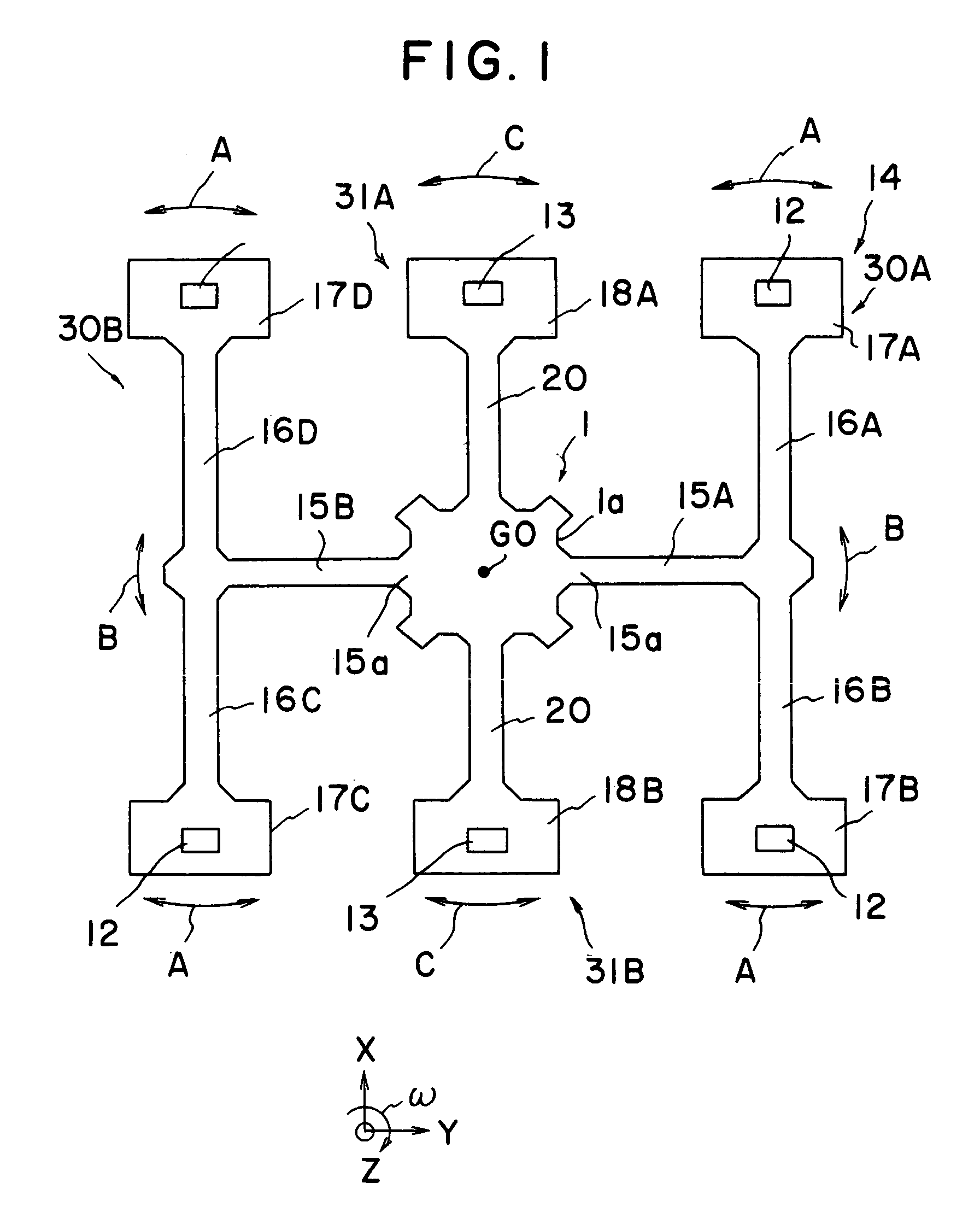
[0024]The shape and motion of a vibrator 14 according to the present embodiment will be described first, referring to FIG. 1. The vibrator 14 has a base part 1, a pair of driving vibration systems 30A, 390B and a pair of detection vibration systems 31A, 31B. The base part 1 of the present example has a square shape of quad-symmetrical with respect to the center of gravity GO (the center of gravity when the vibrator is not vibrated) of the vibrator. The driving vibration systems 30A, 30B and detection vibration systems 31A, 31B are protruded from the fixing part 1, respectively, at the respective sides 1a.

[0025]The driving vibration systems 30A and 30B have elongated supporting portions 15A and 15B protruding from the peripheral part 1a of the base portion 1 in radial directions and a pair of driving vibration arms 16A, 16B and 16C, 16D protruding in a direction perpendicular to the longitudinal direction of the supporting portions 15A and 15B, respectively. According to the present...


PUM


Abstract

The present invention provides a method of measuring a physical quantity using a vibrator. The vibrator has a plurality of driving vibration arms, a plurality of detection vibration arms, films for adjusting a weight provided on the driving vibration arms, and detecting electrodes provided on the detection vibration arms. A driving vibration is excited in the vibrator, and output signals are output from the detecting means based on a detection vibration excited in the vibrator responsive to the physical quantity. The weight of each of the films is adjusted based on a comparison of the output signals from the detection vibration arms.

Description

[0001]This application claims the benefit of Japanese Patent Application P2003-274210 filed on Jul. 14, 2003, the entirety of which is incorporated by reference.BACKGROUND OF THE INVENTION[0002]1. Field of the Invention[0003]The present invention relates to a method and device of measuring a physical quantity.[0004]2. Related Art Statement[0005]In an application of mounting a vibratory gyroscope on a vehicle, the gyroscope is used in an extremely wide temperature range. For example, it is required that the gyroscope properly functions in a wide temperature range of −40° C. to +85° C. Even when the resonance frequency of a pair of bending vibration arms is adjusted at a constant quantity at room temperature, the change and deviation of the resonance frequency may be large as the temperature is considerably changed to a high or low temperature. The change or deviation of resonance frequency thus results in a so-called zero point temperature drift.[0006]The assignee filed a Japanese Pa...

Claims


Application Information

Patent Timeline
Patent Type & Authority Patents(United States)
IPC IPC(8): G01P21/00G01C19/56G01C19/5607G01C19/5628
CPCG01C19/5607
Inventor KIKUCHI, TAKAYUKI
Owner SEIKO EPSON CORP
Why Eureka
Try Eureka