Marine vapor separator with bypass line

a bypass line and vapor separator technology, applied in the direction of fuel injection apparatus, charge feed system, non-fuel substance addition to fuel, etc., can solve the problems of marine applications that are often subject to harsh vibrations and jarring, and cannot supply uninterrupted flow of fuel under all operating conditions, so as to reduce the number of possible fuel leakage points, reduce the risk of fuel leakage, and eliminate the added design and fabrication cost

Active Publication Date: 2007-01-30
CARTER FUEL SYST
View PDF28 Cites 22 Cited by
  • Summary
  • Abstract
  • Description
  • Claims
  • Application Information

AI Technical Summary

Benefits of technology

[0009]The subject invention overcomes the disadvantages of the prior art by eliminating the recirculation of unused fuel through the engine injector system. This, in turn, eliminates the added design and fabrication costs of a prior art style return line, and reduces the risk of fuel leakage.
[0010]According to the invention, a fuel supply system for a marine engine comprises a vapor separator for receiving liquid fuel from a fuel tank and collecting vapors given off from the fuel, a high pressure pump having a fuel inlet for withdrawing liquid fuel from the vapor separator and a fuel outlet, and a fuel delivery line for delivering fuel under pressure from the fuel outlet to an engine injector system. The invention is characterized by a bypass line which extends between the fuel delivery line and the vapor separator for returning excess fuel to the vapor separator prior to its reaching the engine injector system. In this manner, fuel in excess of the demands of the engine injector system is returned directly to the vapor separator thus eliminating the need to recirculate unneeded fuel through the engine injector system.
[0011]By eliminating the prior art return line and substituting in its place the novel bypass line, the number of possible fuel leak points can be reduced.
[0012]The present invention challenges the state-of-the-art presumption that hot fuel in the engine injector system must be cooled to a less volatile temperature by re-mixing with liquid fuel in the vapor separator, and where any fuel vapors can be vented and bled out of the system. The applicant has discovered that the hot fuel concerns are overstated in view of today's cleaner burning, less-volatile fuels required under current clean air legislation. Thus, hot fuel, which typically only becomes a concern during long periods of engine idle, is not problematic when a fuel supply system according to the subject invention is employed.

Problems solved by technology

In fuel supply systems for marine engines, and in particular for so-called in-board and stern drive type engines, it is often challenging to supply an uninterrupted flow of fuel under all operating conditions.
The operating environment is frequently very hot, causing the fuel to vaporize if not carefully controlled.
Furthermore, marine applications are often subject to harsh vibrations and jarring.
Leaked fuel on a marine vessel can, in extreme instances, result in fire which may require immediate human evacuation regardless of the vessel location or weather conditions.
Thus, meeting the fuel demands of a marine engine under these operating conditions and in consideration of these safety issues can be a challenge.
One disadvantage of this technique resides in the requirement to design and fabricate the return line and associated fittings with extremely high quality and durable components to avert the possibility of fuel leakage over the foreseeable service interval of the fuel supply system.
This increases both the cost of the fuel supply system and the risk of leakage, particularly where operating conditions are harsh and service intervals extend beyond manufacturer recommendations.

Method used


Image

  • Marine vapor separator with bypass line
  • Marine vapor separator with bypass line
  • Marine vapor separator with bypass line

Examples


Embodiment Construction

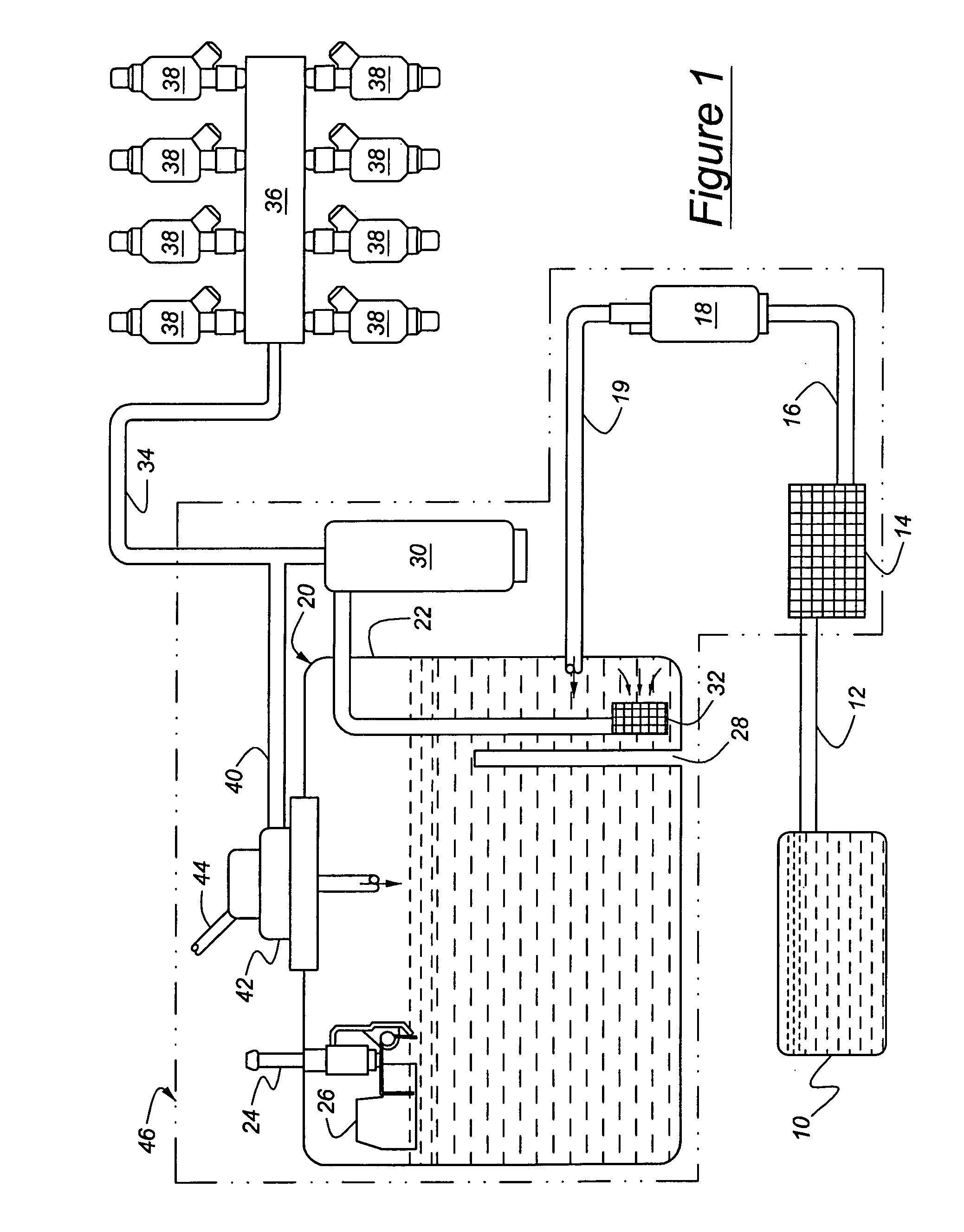
[0016]Referring to the Figures, wherein like numerals indicate like or corresponding parts throughout the several views, a fuel supply system for a marine internal combustion engine in is illustrated schematically in FIG. 1.

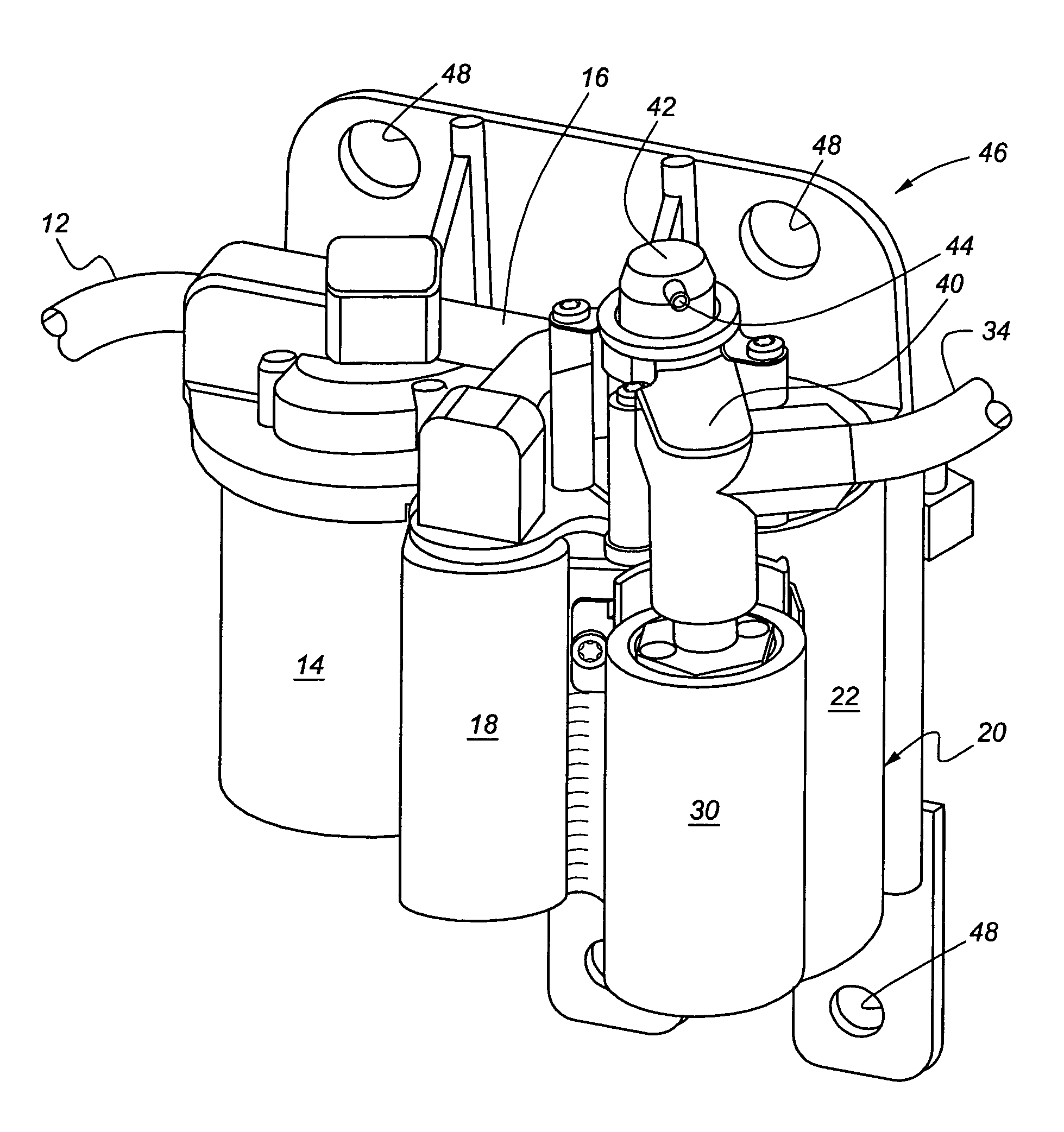
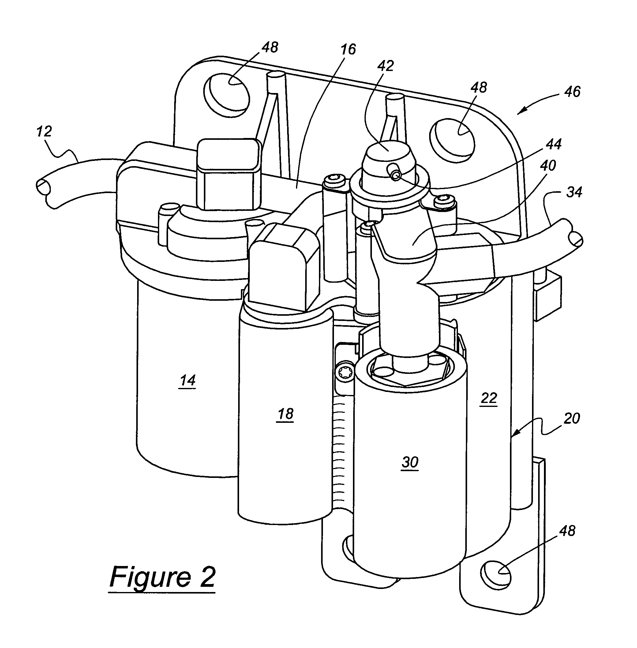
[0017]The fuel supply system includes a fuel tank 10 from which tank-filter line 12 directs fuel to a water filter 14. In the water filter 14, any water present in the fuel is separated. Typically, the water filter 14 is replaced during regular servicing. A filter-pump line 16 routes fuel from the water filter 14 to a low-pressure type lift pump 18. The lift pump 18, in turn, urges fuel through a pump-separator line 19 into a vapor separator, generally indicated at 20.

[0018]The vapor separator 20 thus receives liquid fuel from the fuel tank 10 through this relatively direct distribution system. The primary purpose of the vapor separator 20 is to collect and discharge vapors given off from the fuel. The vapor separator 20 is defined by a housing 22 which is sealed...


PUM


Abstract

In a fuel supply system, liquid fuel is supplied to a marine engine from a fuel tank (10). The fuel first passes through a water filter (14), a lift pump (18) and is temporarily deposited in a vapor separator (20) where vapors given off from the fuel are collected and vented. A high pressure pump (30) withdraws liquid fuel from the vapor separator (200 and delivers it under pressure to an engine injector system (36) via a fuel delivery line (34). The fuel pressure between the high pressure pump (30) and the engine injector system (36) is monitored to determine whether the engine injector system (36) is being presented with more fuel than is required for efficient engine operation. If more fuel than needed is being supplied by the high pressure pump (30), the unneeded fuel is returned to the vapor separator (20) through a bypass line (40). A pressure regulator (42) along the bypass line (40) prevents the return of fuel to the vapor separator (20) when the pressure differential between the vapor separator (20) and the fuel being delivered to the engine injector system (36) reaches a predetermined value. The bypass line (40) comprises a short path from the fuel delivery line (34) and returns fuel back into the vapor separator (20) without traversing large spaces. The water filter (14), lift pump (18), vapor separator (20), high pressure pump (30), by-pass line (40) and pressure regulator (42) are contained as an integral unit (46).

Description

BACKGROUND OF THE INVENTION[0001]1. Field of the Invention[0002]The subject invention relates to a system for supplying fuel under pressure to an internal combustion engine in a marine vessel, and, more specifically, addresses the problem of controlling fuel delivery to a fuel injection system in a marine engine.[0003]2. Description of the Prior Art[0004]In fuel supply systems for marine engines, and in particular for so-called in-board and stern drive type engines, it is often challenging to supply an uninterrupted flow of fuel under all operating conditions. The operating environment is frequently very hot, causing the fuel to vaporize if not carefully controlled. And fuel delivery must be compatible with marine engine run cycles which are characterized by long periods of operation at a steady RPM, punctuated by abrupt instances of rapid acceleration or deceleration. Throughout these cycles and conditions, fuel is expected to be delivered to the engine without interruption.[0005]F...

Claims


Application Information

Patent Timeline
Patent Type & Authority Patents(United States)
IPC IPC(8): F02M37/04
CPCF02M37/0047F02M37/20F02M55/002F02B61/04F02M63/0225F02M37/007F02M25/08F02M37/04
Inventor HARVEY, RICHARD W.
Owner CARTER FUEL SYST
Why Eureka
Try Eureka