Vapor separator with integral low pressure lift pump

a technology of vapor separator and lift pump, which is applied in the field of systems, can solve the problems of fuel vaporization if not carefully controlled, difficult to supply uninterrupted flow of fuel under all operating conditions, and marine applications are often subject to harsh vibrations and jarring, so as to eliminate the added design and fabrication costs, eliminate the effect of leakage points and increasing costs

Inactive Publication Date: 2011-07-14
CARTER FUEL SYST
View PDF42 Cites 5 Cited by
  • Summary
  • Abstract
  • Description
  • Claims
  • Application Information

AI Technical Summary

Benefits of technology

[0012]The subject invention overcomes the disadvantages of the prior art by eliminating leakage points and increased costs associated with assembly. Rather, a low pressure lift pump, such as a pulse pump, is integrally formed at least in part with the vapor separator. The pump, for example, may be located internally, externally or partly internally and partly externally to the vapor separator. This, in turn, eliminates the added design and fabrication costs of a prior art, and reduces the risk of fuel leakage.

Problems solved by technology

In fuel supply systems, and in particular for a marine engine having in-board and stern drive type engines, it is often challenging to supply an uninterrupted flow of fuel under all operating conditions.
The operating environment is frequently very hot, causing the fuel to vaporize if not carefully controlled.
Furthermore, marine applications are often subject to harsh vibrations and jarring.
Leaked fuel on a marine vessel can, in extreme instances, result in fire which may require immediate human evacuation regardless of the vessel location or weather conditions.
Thus, meeting the fuel demands of a marine engine under these operating conditions and in consideration of these safety issues can be a challenge.
One disadvantage of this technique resides in the requirement to design and fabricate the return line and associated fittings with extremely high quality and durable components to avert the possibility of fuel leakage over the foreseeable service interval of the fuel supply system.
This increases both the cost of the fuel supply system and the risk of leakage, particularly where operating conditions are harsh and service intervals extend beyond manufacturer recommendations.
In additional to the disadvantages describe above, this system suffers from having a low pressure lift pump 18 located outside of the vapor separator 40.
This requires additional mounting hardware and fuel hose routings, which increase the costs and leakage points of fuel.
Although providing less leakage points than the aforementioned prior art, this system still suffers from leakage points and costs associated with assembly and mounting.

Method used


Image

  • Vapor separator with integral low pressure lift pump
  • Vapor separator with integral low pressure lift pump
  • Vapor separator with integral low pressure lift pump

Examples


Embodiment Construction

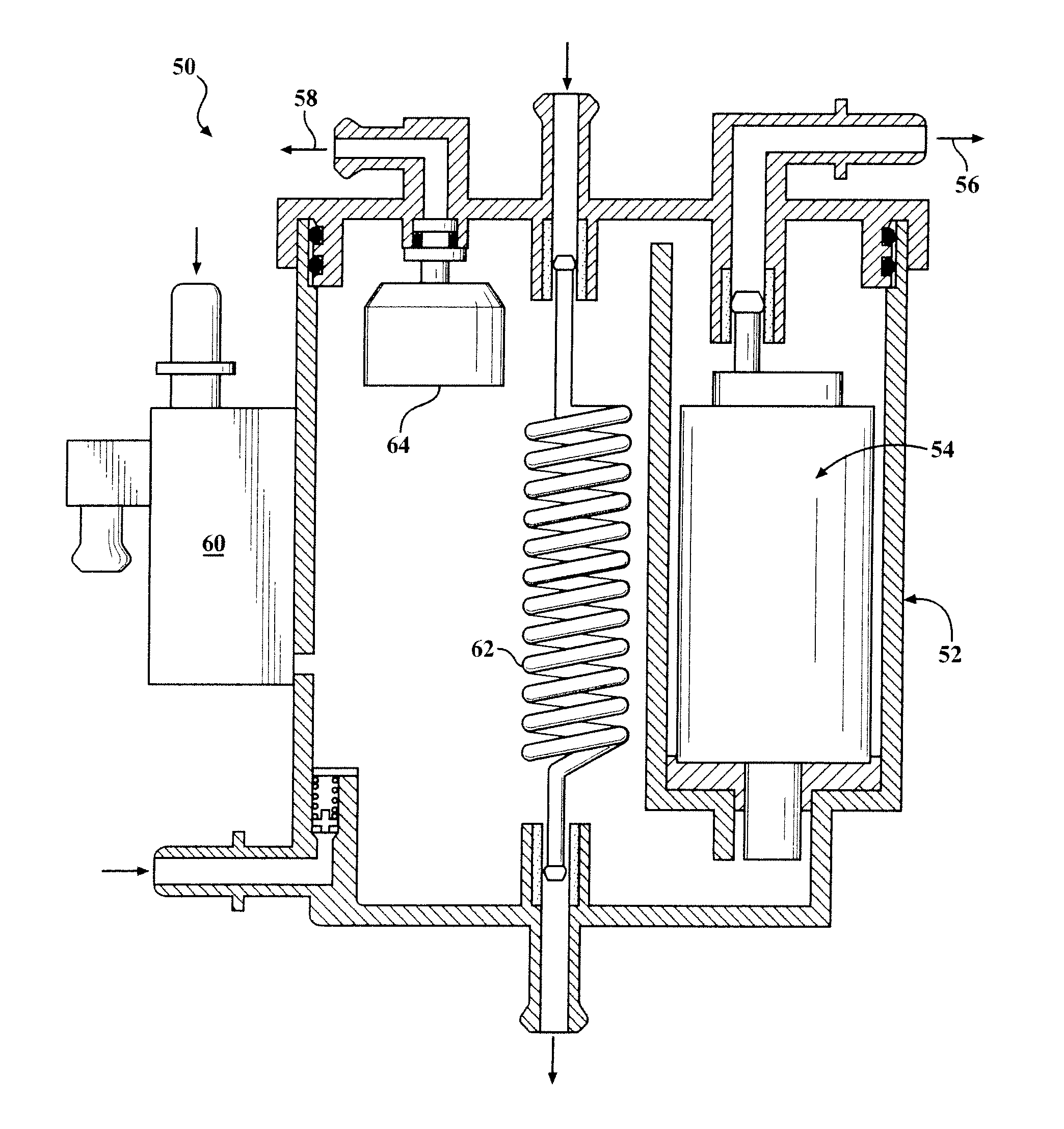
[0020]Referring to the Figures, wherein like numerals indicate like or corresponding parts throughout the several views, a fuel supply system for a marine internal combustion engine in is illustrated schematically in FIG. 3.

[0021]FIG. 3 illustrates a fuel vapor separator 50 having a main body 52 formed of polymeric materials that is adapted to received a supply of liquid fuel and provide a substantially vapor free supply of liquid fuel to fuel pump 54. The fuel pump 54 is preferably carried by the fuel vapor separator 50 and may be an electric motor driven fuel pump having an inlet in communication with the supply of liquid fuel in the main body 52 and an outlet 56 through which pressurized fuel is discharged for delivery to an engine. Fuel is pumped from a tank using a low pressure lift pump 60 into a reservoir of the vapor separator 50. The low pressure lift pump 60 is formed integrally with the vapor separator 50. That is, at least part of the low pressure lift pump is formed fro...


PUM


Abstract

A system for supplying fuel under pressure to an internal combustion engine, and to control fuel delivery to a fuel injection system in an internal combustion engine having a low pressure pump formed integrally as at least part of a main housing of a vapor separator assembly. The low pressure pump lifts fuel into a cavity of a reservoir, which is drawn from a high pressure pump into the internal combustion engine. Due to the integrated nature of the low pressure pump, leak paths and assembly costs are reduced.

Description

CLAIM FOR PRIORITY[0001]This application claims the benefit of priority to U.S. Ser. No. 61 / 293,363, filed Jan. 8, 2010, the contents of which are hereby incorporated by reference.BACKGROUND OF THE INVENTION[0002]1. Field of the Invention[0003]The subject invention relates to a system for supplying fuel under pressure to an internal combustion engine, and, more specifically, to controlling fuel delivery to a fuel injection system in an internal combustion engine having a low pressure pump formed integrally as at least part of a main housing of a vapor separator assembly.[0004]2. Description of the Prior Art[0005]In fuel supply systems, and in particular for a marine engine having in-board and stern drive type engines, it is often challenging to supply an uninterrupted flow of fuel under all operating conditions. The operating environment is frequently very hot, causing the fuel to vaporize if not carefully controlled. And fuel delivery must be compatible with marine engine run cycle...

Claims


Application Information

Patent Timeline
Patent Type & Authority Applications(United States)
IPC IPC(8): F02M37/20
CPCF02M25/08F02M37/20F02M37/14F02M37/08B60K15/035
Inventor ACHOR, KYLE DEAN
Owner CARTER FUEL SYST
Why Eureka
Try Eureka