Liquid handling system

a technology of liquid handling system and liquid dispensing, which is applied in the field of liquid handling system, can solve the problems of large proportion of deaths, and significant proportions of deaths due to water pollution, and achieve the effect of facilitating a controlled flow rate transfer

Inactive Publication Date: 2007-01-30
MCROBERT IAN
View PDF8 Cites 7 Cited by
  • Summary
  • Abstract
  • Description
  • Claims
  • Application Information

AI Technical Summary

Benefits of technology

[0003]The present invention was developed with a view to providing a liquid handling system that can facilitate a controlled flow rate transfer of liquid between receptacles or tanks with minimal mixing or turbulence.

Problems solved by technology

The larvae are particularly stress sensitive and it is common for a large proportion to die during this procedure.
On the other hand, if the larvae are not transferred, to allow cleaning of the tank and removal of waste products, significant proportions will die due to water pollution.

Method used


Image

  • Liquid handling system
  • Liquid handling system
  • Liquid handling system

Examples


second embodiment

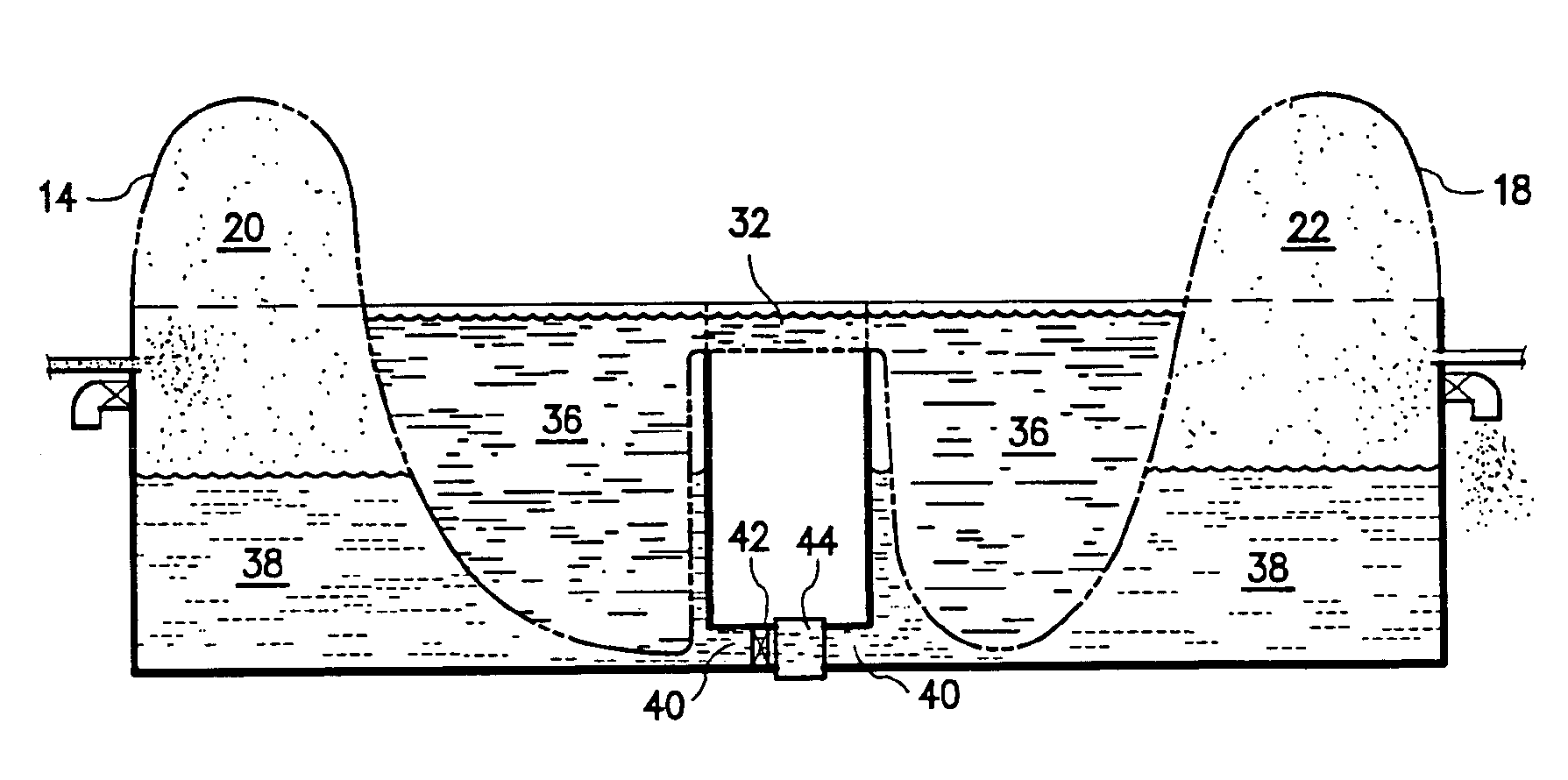
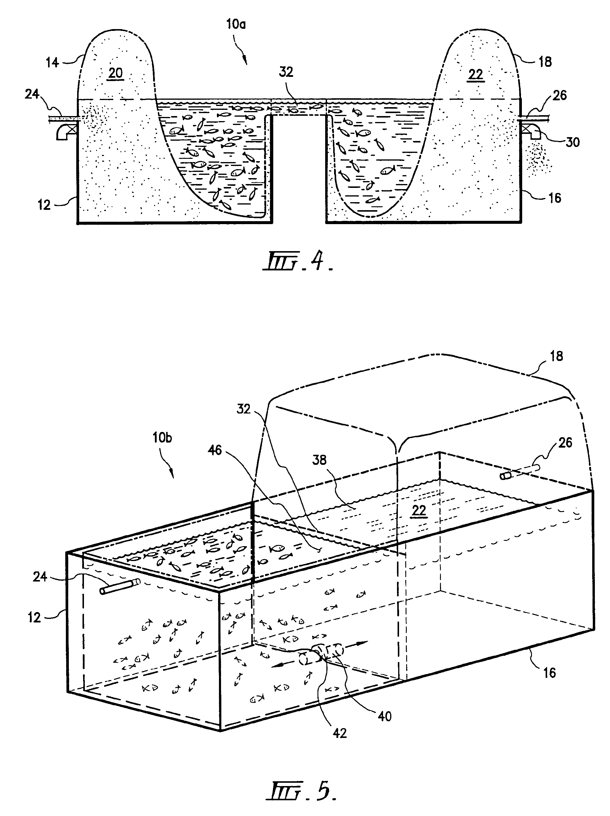
[0041]The provision of the ballast liquid 38 is optional. In the system 10a depicted in FIG. 4 in which like reference numbers denote like features, the system 10 contains no ballast liquid. Rather, with the system 10a in its initial state, the region 22 is simply filled completely with a gas such as air. In the event that the system 10a does not require or use the liquid ballast 38 then additionally it will not require the second path 40, valve 42 and pump 44. In the system 10a fish are contained within the water being transferred between tanks 12 and 16. If the initial state of the system 10a is with the liner 14 in the lining position and the liner 18 in the inverted position so that the tank 12 contains the water holding the fish, the water and fish are transferred to the tank 16 by supplying air to the region 20 displacing the water to flow through channel 32 onto liner 18. With the air vent 30 open, the liner 18 progressively sinks toward the lining position as the water and f...

embodiment 10

[0047]FIG. 7 depicts a further embodiment of the system 10d which differs in substance from the embodiment 10 depicted in FIGS. 1–3 by the inclusion of a liquid ballast return channel 54 in both of the tanks 12, 16 each of which is in fluid communication with the second channel 40. The liquid ballast return channels 54 provide a path of minimal resistance for flow of the ballast liquid 38 between the tanks during a transfer cycle. Each tank 12, 16 has a base 56 and a side wall 58 extending upwardly from the base 56. The liquid ballast return channel 54 is formed at the bottom of each tank 12, 16 on or about the base 56. In the system 10d, the channel 54 is formed by providing a false bottom 60 parallel to and spaced above the base 56. The false bottom 60 can take many different forms such as a plate provided with a plurality of holes or slots; a grid; or a plurality of longitudinally extending and laterally spaced apart beams. The false bottom 60 supports the corresponding line of 1...


PUM


Abstract

A liquid handling system transfers liquid (e.g. water, bearing marine animals) between two tanks each having a respective liner which is movable between a lining position (when filled with liquid) and an inverted position (when its respective tank is emptied). In an initial state, liquid is held in a first tank. By supplying air to a space between the first tank and its liner, its liner is progressively lifted and liquid passes along a channel onto the initially inverted second liner (which acts as a baffle to slow the liquid flow). Air in a space between the second liner and the second tank is vented so transferred liquid sinks the second liner to fill the second tank. A ballast liquid may be used in the spaces. Initially held in the second tank, the ballast liquid flows via a passage into the first tank as transfer of liquid progresses.

Description

FIELD OF THE INVENTION[0001]The present invention relates to a liquid handling system particularly, but not exclusively, suited to transferring liquid between a plurality of receptacles.BACKGROUND OF THE INVENTION[0002]In land based aquaculture systems there is often a need to transfer marine animals from one tank or receptacle to another. This may be done for grading purposes or to allow cleaning of, and removal of waste products and debris from, a tank. For example in the harvesting of crustacean larvae, the larvae must be regularly shifted from tank to tank to allow cleaning. At present, this is performed by manually transferring the larvae by a pipette to a holding vessel. The larvae are particularly stress sensitive and it is common for a large proportion to die during this procedure. On the other hand, if the larvae are not transferred, to allow cleaning of the tank and removal of waste products, significant proportions will die due to water pollution. The greater the time bet...

Claims


Application Information

Patent Timeline
Patent Type & Authority Patents(United States)
IPC IPC(8): A01K61/00B67D5/00A01K63/00B67D99/00
CPCA01K63/00Y10T137/3127Y10T137/469Y10T137/86187
Inventor MCROBERT, IAN
Owner MCROBERT IAN
Why Eureka
Try Eureka