
Thermoplastic extrusion with vapor barrier and surface sulfonation

a technology of surface sulfonation and thermoplastic pipe, which is applied in the direction of pipes, pipes/joints/fittings, mechanical equipment, etc., can solve the problems of degrading the overall performance of the overwrap in time, and achieve the effect of reducing the permeability of the inner thermoplastic pip

Inactive Publication Date: 2014-07-03
THERCOM HLDG
View PDF15 Cites 12 Cited by
  • Summary
  • Abstract
  • Description
  • Claims
  • Application Information

AI Technical Summary

Benefits of technology

This patent is about reinforced thermoplastic extrusions and methods of manufacturing them. These extrusions have a reinforcing layer made of thermoplastic plastic that can be blown or extruded into a shape and then reinforced to make it stronger. The extrusions also have a vapor barrier to prevent the transfer of volatile hydrocarbons that might affect the performance of the reinforcing layer. The vapor barrier can be made of organic or inorganic materials like ethylene vinyl alcohol or graphene. The reinforced thermoplastic extrusions can be used for a variety of applications like pipes for gas or water distribution. One specific embodiment provides an intermediate vapor barrier between the inner thermoplastic pipe and the outer thermoplastic reinforcing layer to limit the transfer of volatile hydrocarbons. This improves the elongation-to-break ratio of the extrusion, making it more durable and better suited for use as a coiled pipe.

Problems solved by technology

Under high pressures, volatile hydrocarbons transported through the extruded thermoplastic pipe can migrate through the pipe sidewall and chemically attack the thermoplastic overwrap, degrading the overall performance of the overwrap in time.

Method used


Image

  • Thermoplastic extrusion with vapor barrier and surface sulfonation
  • Thermoplastic extrusion with vapor barrier and surface sulfonation
  • Thermoplastic extrusion with vapor barrier and surface sulfonation

Examples


Embodiment Construction

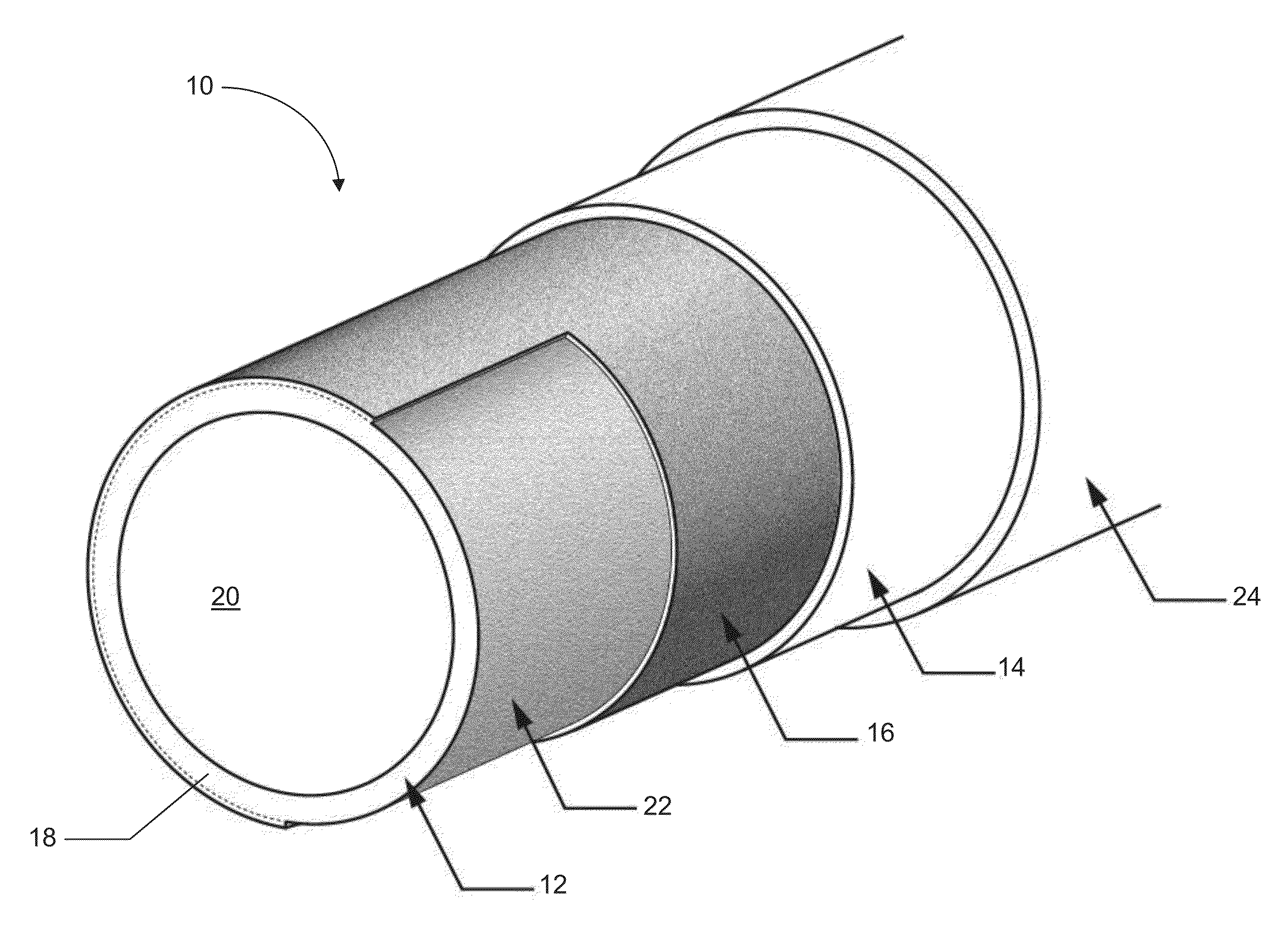
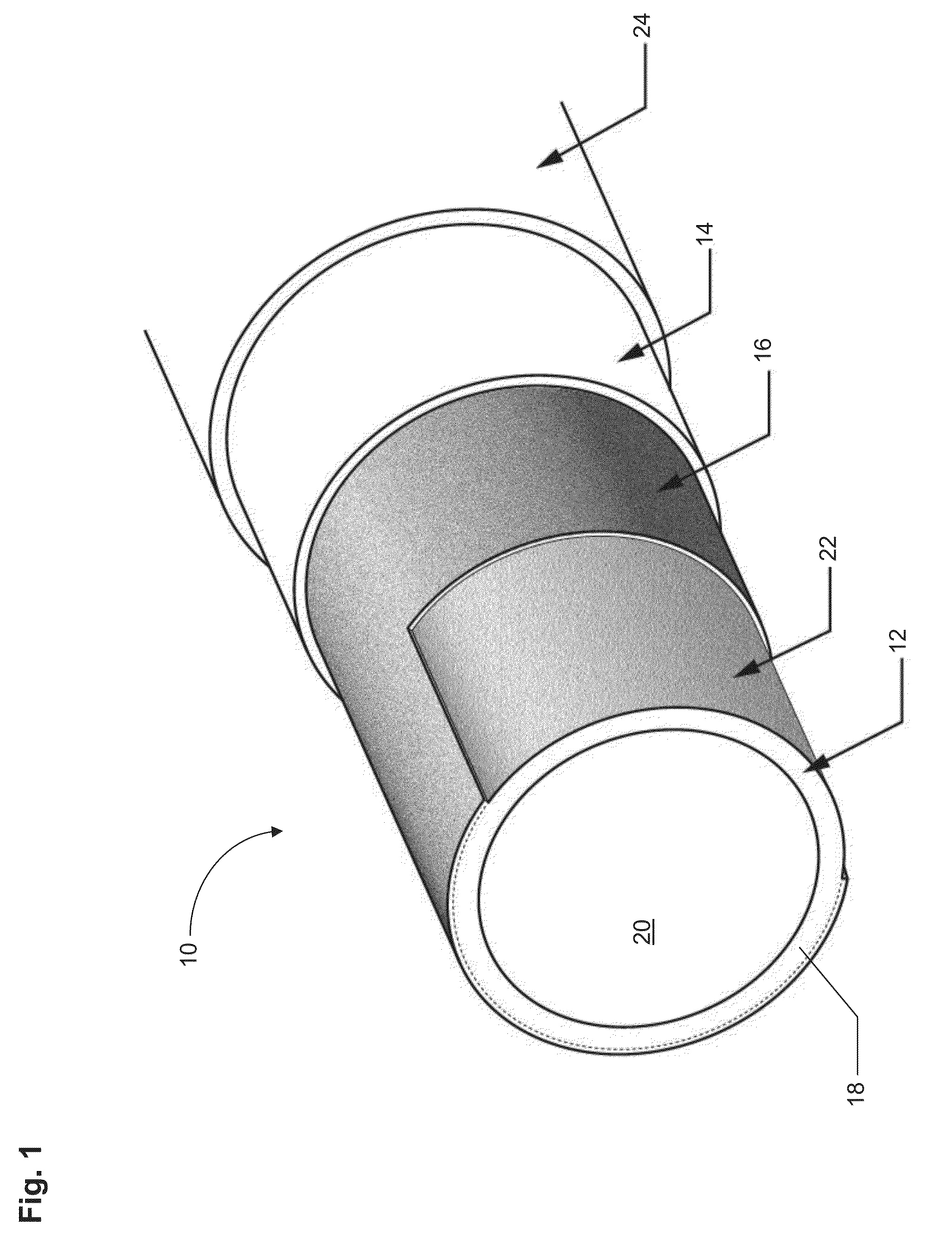
[0016]The invention as contemplated and disclosed herein includes a reinforced thermoplastic extrusion and a related method of manufacture. With reference to FIG. 1, a reinforced thermoplastic extrusion in accordance with one embodiment is illustrated and generally designated 10. The reinforced thermoplastic extrusion includes an inner tubular member 12, a reinforcing layer 14, and a vapor barrier 16 disposed between the tubular member 12 and the reinforcing layer 14.

[0017]More particularly, the inner tubular member 12 is a thermoplastic extrusion in the present embodiment, optionally a high density polyethylene (HDPE) extrusion. The inner tubular member 12 includes a sidewall 18 defining an inner surface 20 and an outer surface 22. The outer surface 22 is spaced apart from the inner surface 20 by a desired sidewall thickness, and is directly or indirectly bonded to the vapor barrier 16. The inner surface 20 forms a conduit for a moving fluid, for example an aqueous fluid, a gaseous...


PUM

PropertyMeasurementUnit
Densityaaaaaaaaaa
Permeabilityaaaaaaaaaa
Elongationaaaaaaaaaa

Abstract

A reinforced thermoplastic extrusion and a related method of manufacture are provided. The reinforced thermoplastic extrusion includes an extruded polymeric member, a thermoplastic reinforcing layer, and an intermediate vapor barrier between the extruded polymeric member and the thermoplastic reinforcing layer. The intermediate vapor barrier is bonded to the exterior of the extruded polymeric member and / or the interior of the thermoplastic reinforcing layer to limit the transfer of volatile hydrocarbons therethrough. Surface sulfonation can additionally be included to decrease the permeability of the thermoplastic extrusion to volatile hydrocarbons and other gases that can affect the performance of the outer thermoplastic reinforcing layer.

Description

BACKGROUND OF THE INVENTION[0001]The present invention relates to high-pressure thermoplastic pipe including a reinforcing overwrap.[0002]Thermoplastic extrusions such as pipes are in many instances overwrapped with a reinforcing material for high pressure applications. For example, a thermoplastic composite overwrap can be bonded to the exterior of an extruded thermoplastic pipe. In use, the overwrap can improve the ability of the extruded thermoplastic pipe to transport a moving fluid at high pressures, including up to 100 bar in some applications.[0003]Under high pressures, volatile hydrocarbons transported through the extruded thermoplastic pipe can migrate through the pipe sidewall and chemically attack the thermoplastic overwrap, degrading the overall performance of the overwrap in time. In other instances, agents that are added to aid in extrusion or performance can inhibit the bonding of the reinforcing overwrap to the thermoplastic pipe. The same interaction can also cause ...

Claims


Application Information

Patent Timeline
IPC IPC(8): F16L9/14
CPCF16L9/14F16L9/123
Inventor DYKSTERHOUSE, JOEL A.
Owner THERCOM HLDG
Learn More