Sample liquid analytical chip

a liquid analytical and chip technology, applied in the field of analysis chips, can solve problems such as damage to storage stability, and achieve the effect of simple structure, excellent accuracy and quick measuremen

Inactive Publication Date: 2010-03-11
PANASONIC CORP
View PDF3 Cites 12 Cited by
  • Summary
  • Abstract
  • Description
  • Claims
  • Application Information

AI Technical Summary

Benefits of technology

[0023]The present invention provides a sample liquid analysis chip and analysis method thereof that has a reaction area and a detection area apart from each other in a simple structure, that is capable of controlling the transfer of sample liquid, and that is excellent in accurate and quick measurement.

Problems solved by technology

However, with the above-described sensor, when a number of reagents is used, mixing reagents in advance may damage storage stability.

Method used


Image

  • Sample liquid analytical chip
  • Sample liquid analytical chip
  • Sample liquid analytical chip

Examples


example 1

Cholesterol Sensor Shown in FIG. 3

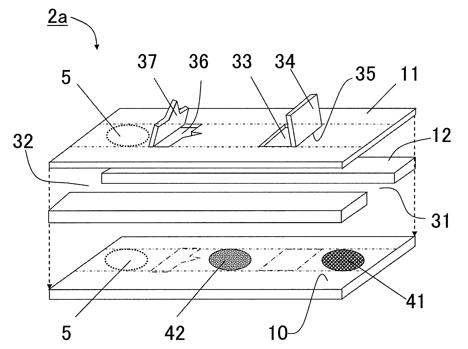
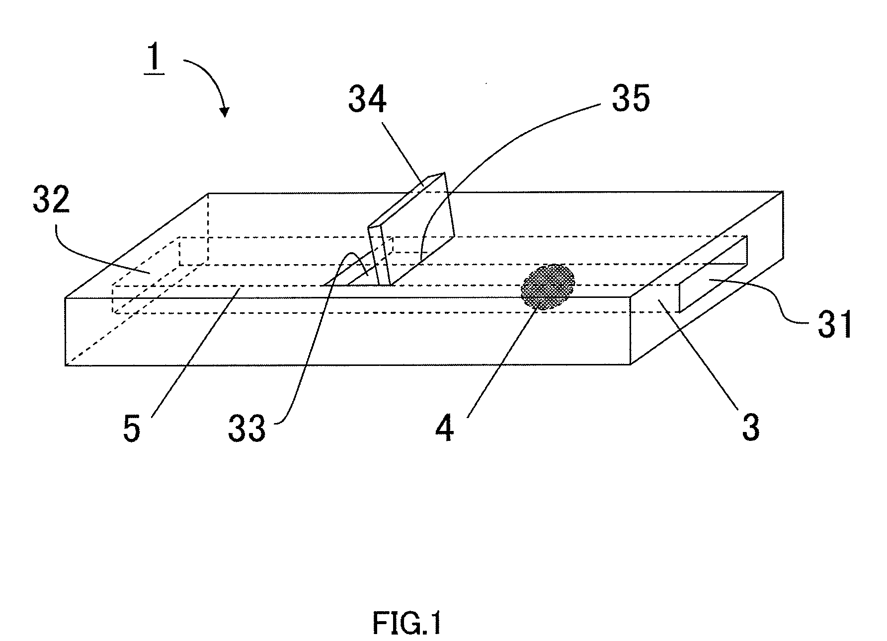
[0117]A polycarbonate ceiling plate having a thickness of 0.1 mm, a length of 5 mm and a width of 3 mm was prepared. A plan view of a cuts was inputted to a GRPHTEC cutting plotter, to form the cut in the shapes shown in FIGS. 2A and 2E on the prepared ceiling plate. The formed cut parts were bent as shown in FIG. 3, to form lids (34 and 37) and openings (33 and 36). Hinges (35 and 38) were bent to be whitened so that the lids were left open. The distance from sample liquid inlet 31 to hinge 35 of first opening 33 was 1 mm, and the distance from hinge 38 of second opening 36 to air hole 32 was also 1 mm.

[0118]The width of the sample liquid flow path was 0.8 mm, and the width of lids 34 and 37 was 0.8 mm. The hinge of lid 34 was placed upstream of the part opposing the hinge of opening 33. The hinge of lid 37 was placed downstream of the part opposing the hinge of opening 36. A projection of an isosceles triangle having an apex of 30° and a height of...

example 2

Cholesterol Sensor Shown in FIG. 5

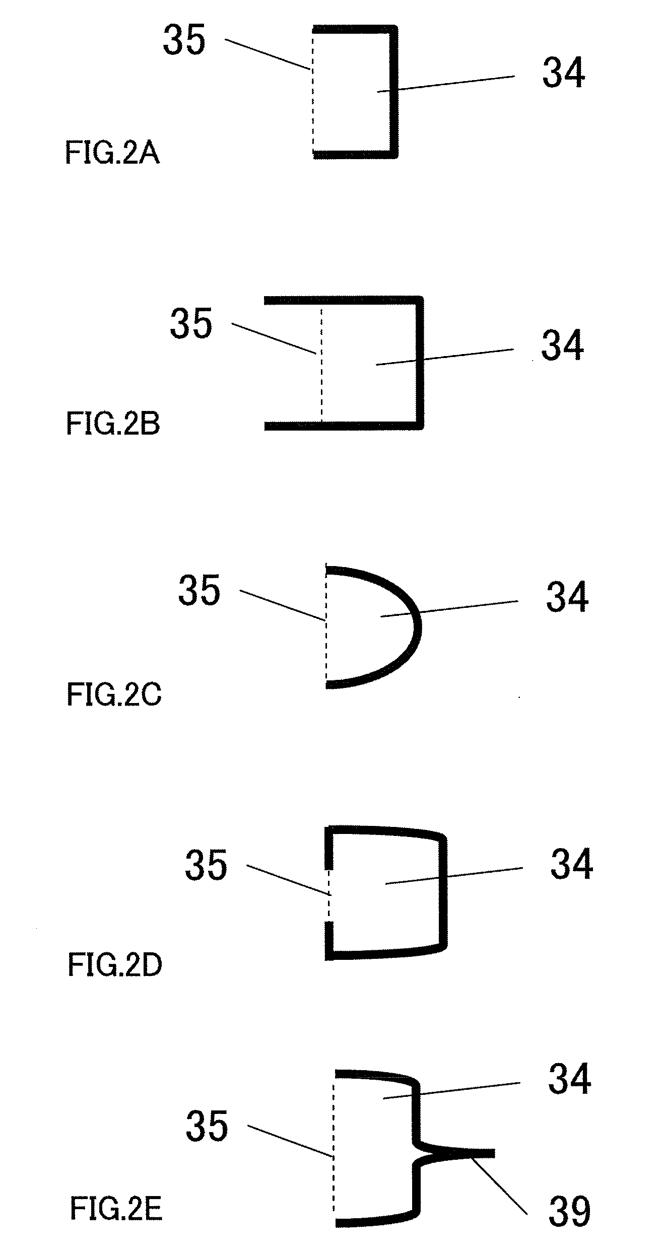
[0129]A motherboard, a ceiling plate, spacers were prepared as shown in FIG. 5 as in Example 1. The ceiling plate was made of PET. Further, four systems of electrodes were formed on motherboard 1 as shown in FIG. 5. These electrodes were made by masking patterns made of stainless steel and by forming a palladium film in a sputtering apparatus. The motherboard had the same width as the ceiling, and had a length of 7.5 mm, which was longer than the ceiling plate. For that reason, when the motherboard and the spacers were pasted together, the motherboard stuck out 2.5 mm from the side of air hole 32.

[0130]Terminals (510 to 540) were placed in the area up to 1.5 mm from the downstream end of the part where the motherboard was stuck, to made a connecting part with the outside. Each terminal in the connecting part had a width of 0.5 mm. The interval between each terminal in the connecting part was 0.2 mm. Terminals 510 to 540 were provided in order of 510...

example 3

Examination of the Position of the Hinges

[0140]A cholesterol sensor was made in the same manner as in Example 2. However, the structures of the first opening and the lid were switched to the structures of the second opening. That is, first lid 34 was prepared such that hinge 35 was placed in the downstream of the upstream end of opening 33. A projection of an isosceles triangle having an apex of 30° and a height of 0.3 mm was provided in lid 34, and a notch of the same shape to fit in this was provided in opening 33. Second lid 37 was provided such that the hinge was placed the upstream of the downstream end of opening 36. Lid 37 had a rectangle shape without projections. Opening 36 had a rectangle shape fitting in this lid. A notch having the same shape as the lid was provided.

[0141]The sample liquid analysis chip having a lid, which had the same square shape as first lid 34 in Example 2 and whose hinge was placed parallel to the flow path was prepared, and the same experiment was ...


PUM

PropertyMeasurementUnit
contact angleaaaaaaaaaa
widthaaaaaaaaaa
widthaaaaaaaaaa

Abstract

A sample liquid analytical chip that whilst being of simple structure, has a reaction region and a detection region isolated from each other and further has liquid feed control means for a sample liquid, thereby realizing speedy reliable analysis. The sample liquid analytical chip comprises a tubular sample liquid transfer channel with its both ends open, a reaction reagent layer disposed on the internal wall surface of the sample liquid transfer channel and a detection region for detecting any physical or chemical change of the sample liquid. In the sample liquid analytical chip, the sample liquid transfer channel at an area of its wall surface is provided an opening and a lid fitted to the opening. Portion of the lid forms a hinge in cooperation with the wall surface.

Description

TECHNICAL FIELD[0001]The present invention relates to an analysis chip that allows a liquid sample to react with a solid reagent to analyze the liquid sample.BACKGROUND ART[0002]In recent years, advanced analysis technology and testing technology have enabled various types of substances to be measured. Particularly, in the fields of clinical testing, development of measurement systems based on specific reactions such as biochemical reactions, enzyme reactions and antigen-antibody reactions has made it possible to measure substances in bodily fluids, which reflects clinical conditions. The field of clinical testing called “Point of Care Testing (POCT)” is particularly popular. In POCT, various efforts for simple and quick measurement are directed to shortening the period from when a sample is collected until the testing result is found out. That is, POCT requires measurement apparatuses that adopt simple measurement systems, that is compact and portable, and that offers good operabil...

Claims


Application Information

Patent Timeline
Patent Type & Authority Applications(United States)
IPC IPC(8): C12Q1/00G01N31/22C12M1/34G01N21/00H01R43/00
CPCB01L3/502707B01L3/502715B01L3/502738B01L2200/027B01L2200/0621B01L2300/043Y10T29/49117B01L2300/0825B01L2300/087B01L2400/0406B01L2400/0633B01L2400/0688G01N33/558B01L2300/0645
Inventor YAMAMOTO, TOMOHIROYUKIMASA, TETSUOHAMADA, RYOUKITAWAKI, FUMIHISAOZAKI, NOBUHIKO
Owner PANASONIC CORP
Why Eureka
Try Eureka