Power hand tool

a hand tool and power technology, applied in the field of hand tools, can solve the problems of damage to the torque setting mechanism and failure of the impact mechanism to function, and achieve the effect of preventing damage to the torque setting mechanism and preventing damag

Inactive Publication Date: 2007-01-30
MOBILETRON ELECTRONICS
View PDF8 Cites 54 Cited by
  • Summary
  • Abstract
  • Description
  • Claims
  • Application Information

AI Technical Summary

Benefits of technology

[0008]The present invention has been accomplished under the circumstances in view. It is therefore one object of the present invention to provide a power hand tool having a torque control mechanism and an impact mechanism, which allows switching of the impact mechanism between the working position and the non-working position.
[0009]To achieve this object of the present invention, the power hand tool comprises a housing that accommodates a motor, a transmission gear set, a torque control mechanism, and an impact mechanism therein. The torque control mechanism has an adjustment device that is movable between a first position and a second position inside the housing by a rotation action to set the output torque of the power hand tool. The output torque of the power hand tool is at the minimum condition and the adjustment device stops the impact mechanism from working to prevent destruction to the torque setting of the power hand tool when the adjustment device is in the second position.

Problems solved by technology

However, when arranging these two mechanisms in a power hand tool, the functioning of the torque setting mechanism may be damaged when starting the impact mechanism, and the impact mechanism fail to function when started the torque setting mechanism.

Method used


Image

  • Power hand tool
  • Power hand tool
  • Power hand tool

Examples


Embodiment Construction

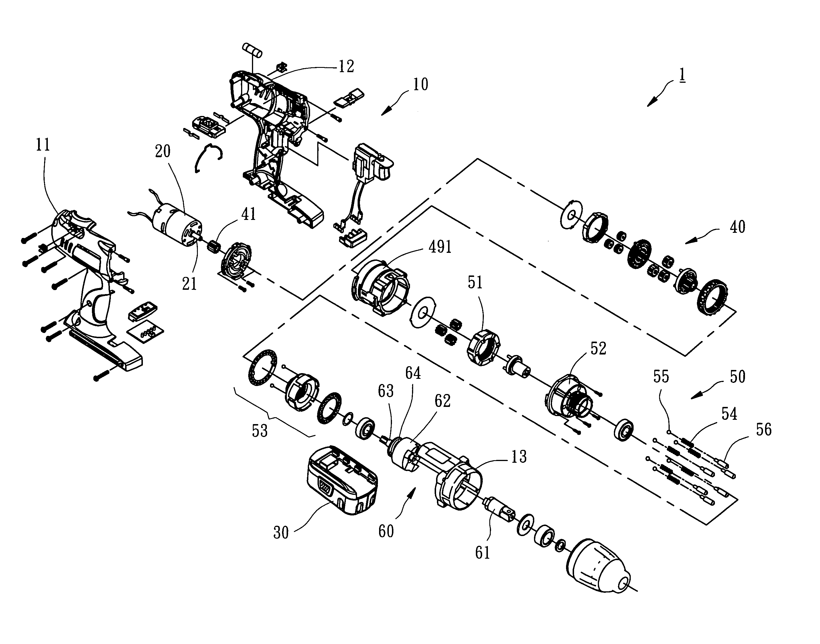
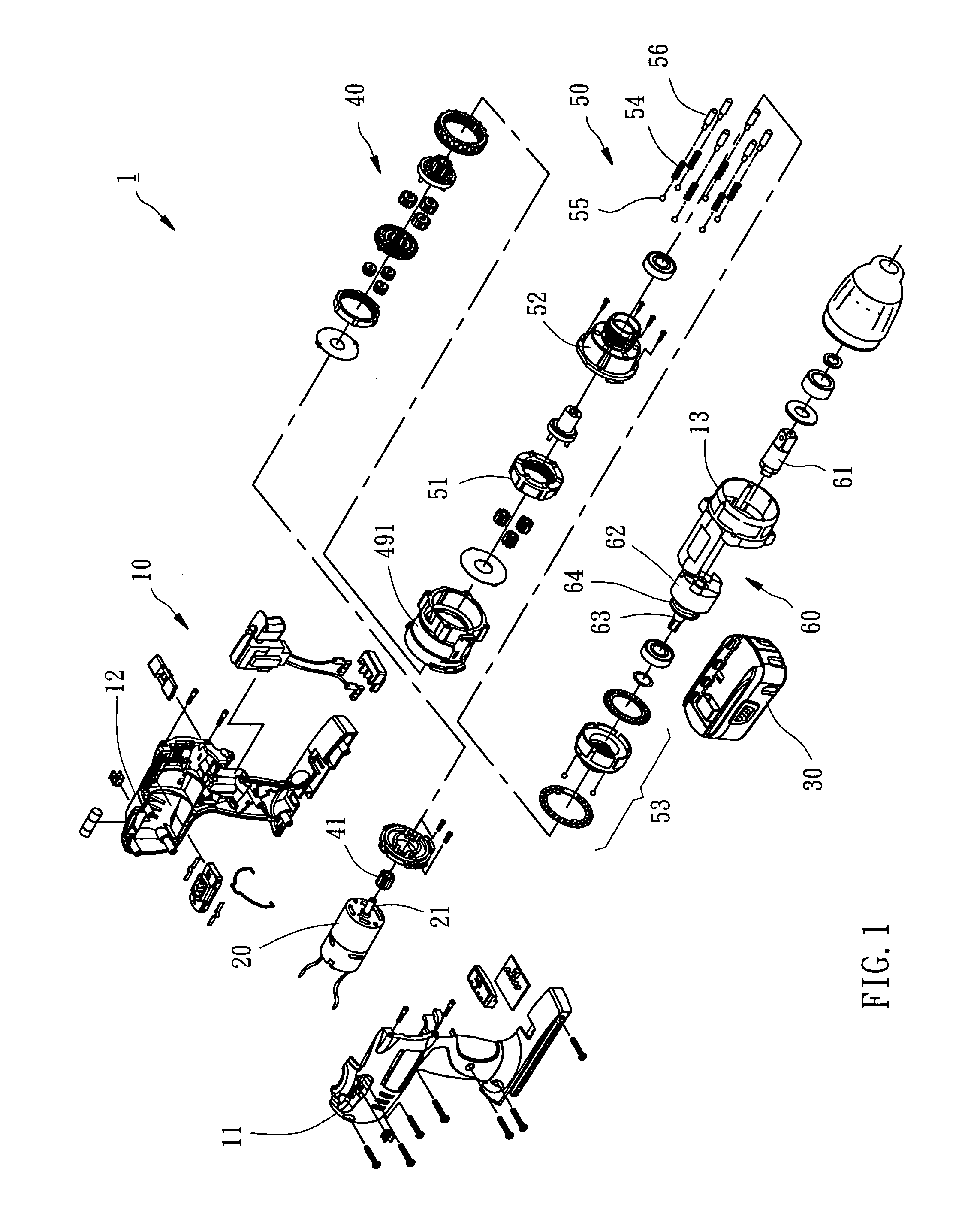
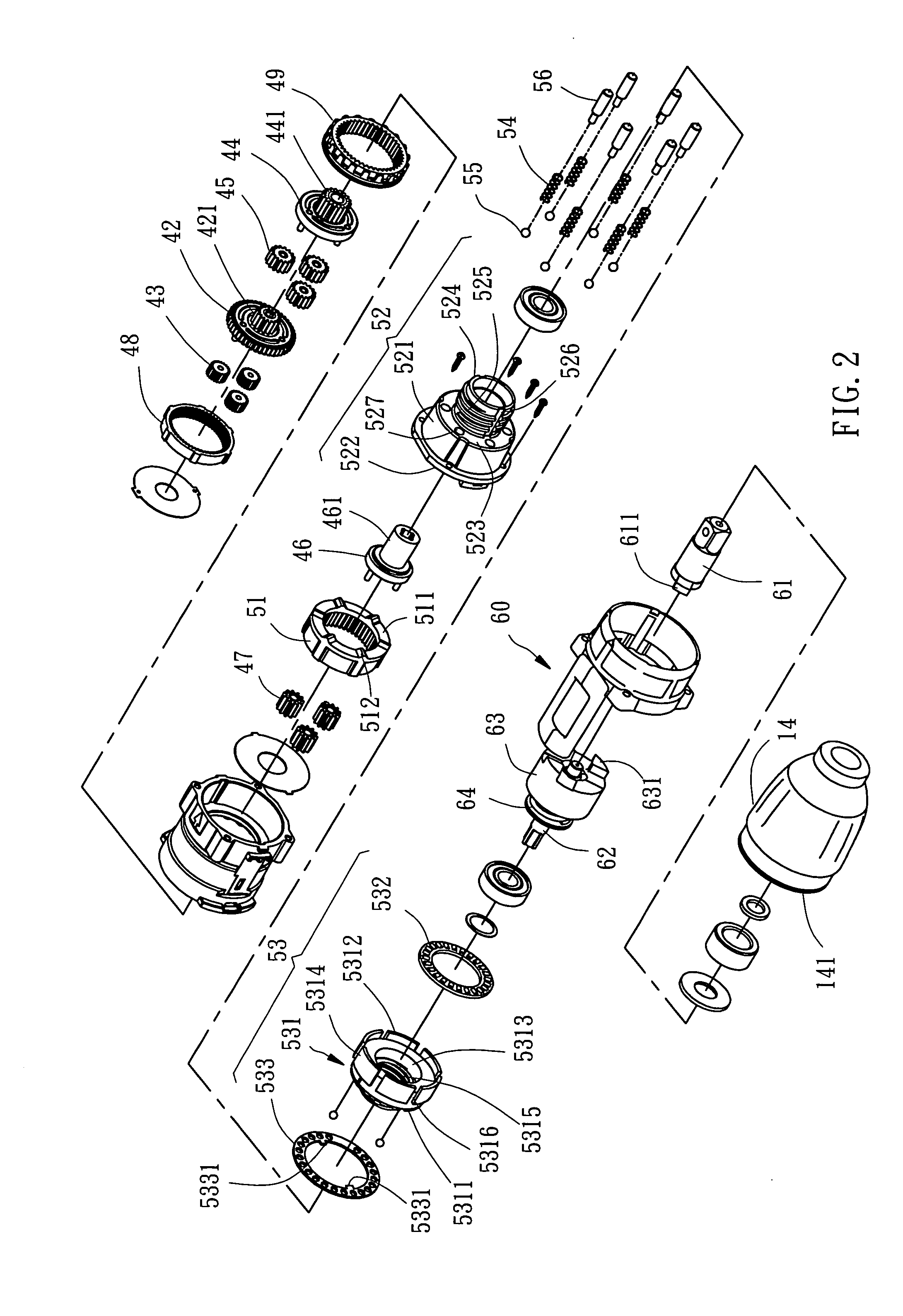
[0014]Referring to FIGS. 1–3, a power hand tool 1 in accordance with the present invention is shown comprised of a housing 10, a motor 20, a battery pack 30, a transmission gear set 40, a torque control mechanisms 50, and an impact mechanism 60.

[0015]The housing 10 is comprised of a left half shall 11, a right half shell 12, a front shell 13, and a front cap 14. The left half shell 11 and the right half shell 12 are abutted against each other. The front shell 13 is fastened to the front side of the abutted left half shell 11 and right half shell 12. The front cap 14 has a rear coupling flange 141 pivotally coupled to the inside wall of the front shell 13 in front of the left half shell 11 and the right half shell 12 for allowing rotary motion of the front cap 14 relative to the front shell 13, and a plurality of locating blocks 142 equiangularly spaced around the inside wall.

[0016]The motor 20 is fixedly mounted inside the housing 10, having a motor shaft 21.

[0017]The battery pack 3...


PUM


Abstract

A power hand tool includes a housing that houses a motor, a transmission gear set, a torque control mechanism and an impact mechanism. The torque control mechanism has an adjustment device that is movable between a first position and a second position inside the housing by a rotation action to set a predetermined output torque of the power hand tool. The output torque of the power hand tool is at the minimum condition and the adjustment device stops the impact mechanism from working to prevent destruction to the torque setting of the power hand tool when the adjustment device is in the second position.

Description

BACKGROUND OF THE INVENTION[0001]1. Field of the Invention[0002]The present invention relates to power hand tools and more particularly, to a power hand tool having a torque control mechanism and an impact mechanism.[0003]2. Description of the Related Art[0004]A conventional power impact wrench is known comprising a motor, a transmission gear set, and an impact mechanism. The transmission gear set reduces the revolving speed of the rotary driving force of the motor to a predetermined level for output. The impact mechanism is adapted to produce an impact against the output shaft of the power hand tool intermittently and rapidly in same direction of rotation when the output shaft of the power hand tool encountered a resisting force that surpasses the output torque, for enabling the output shaft to overcome the resisting force and to keep working.[0005]There is known an electric screwdriver, which comprises a motor, a transmission gear set, and a torque control mechanism. The transmiss...

Claims


Application Information

Patent Timeline
Patent Type & Authority Patents(United States)
IPC IPC(8): B25D11/00
CPCB25B21/00B25B23/1405B25B21/02
Inventor TENG, CHENG-I
Owner MOBILETRON ELECTRONICS
Why Eureka
Try Eureka