
Vehicle exterior mirror system with signal light

a technology for exterior mirrors and vehicles, applied in pedestrian/occupant safety arrangements, lighting and heating devices, instruments, etc., can solve the problem that the pattern generated by the signal light cannot be substantially observed by the driver of the vehicl

Inactive Publication Date: 2007-01-30
MAGNA MIRRORS OF AMERICA INC
View PDF143 Cites 216 Cited by
  • Summary
  • Abstract
  • Description
  • Claims
  • Application Information

AI Technical Summary

Benefits of technology

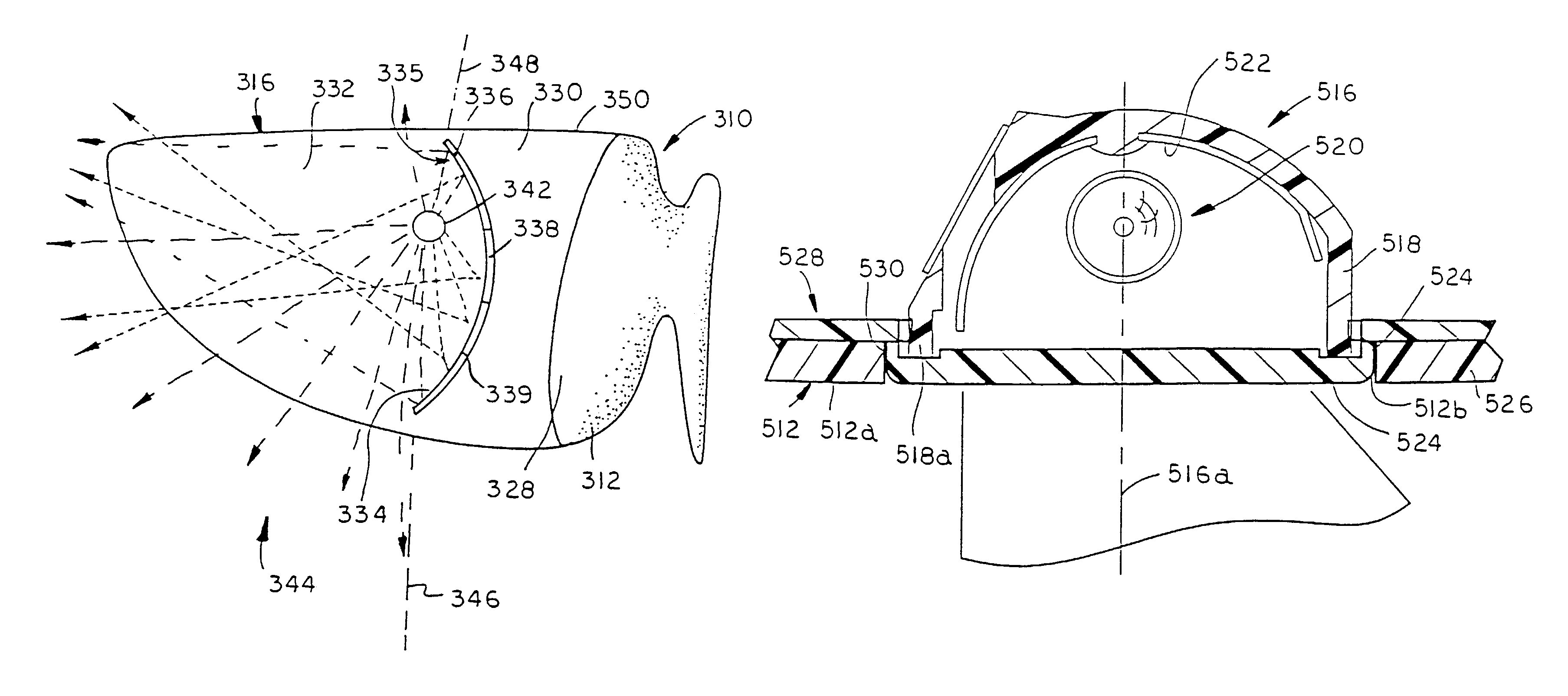
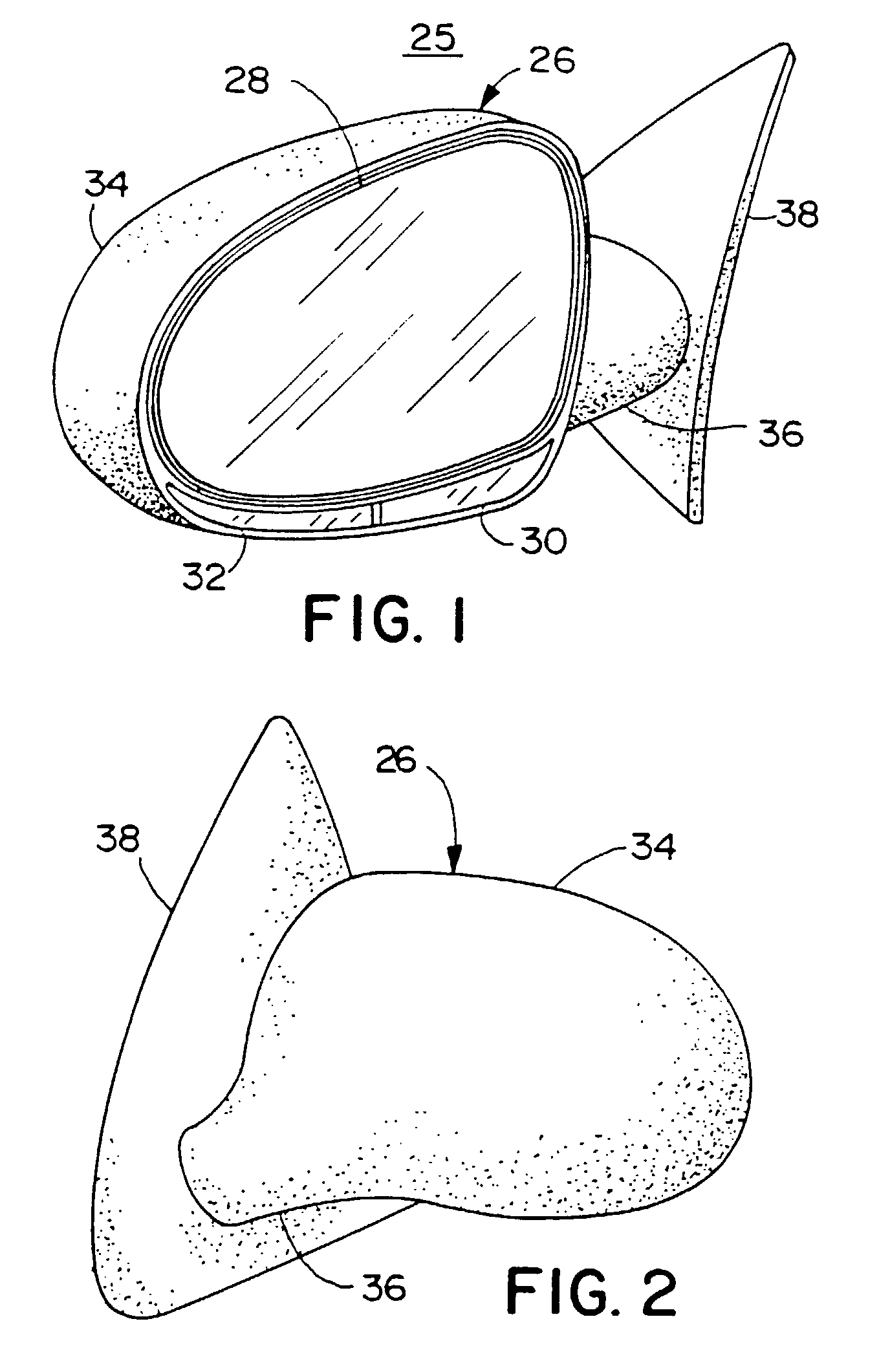
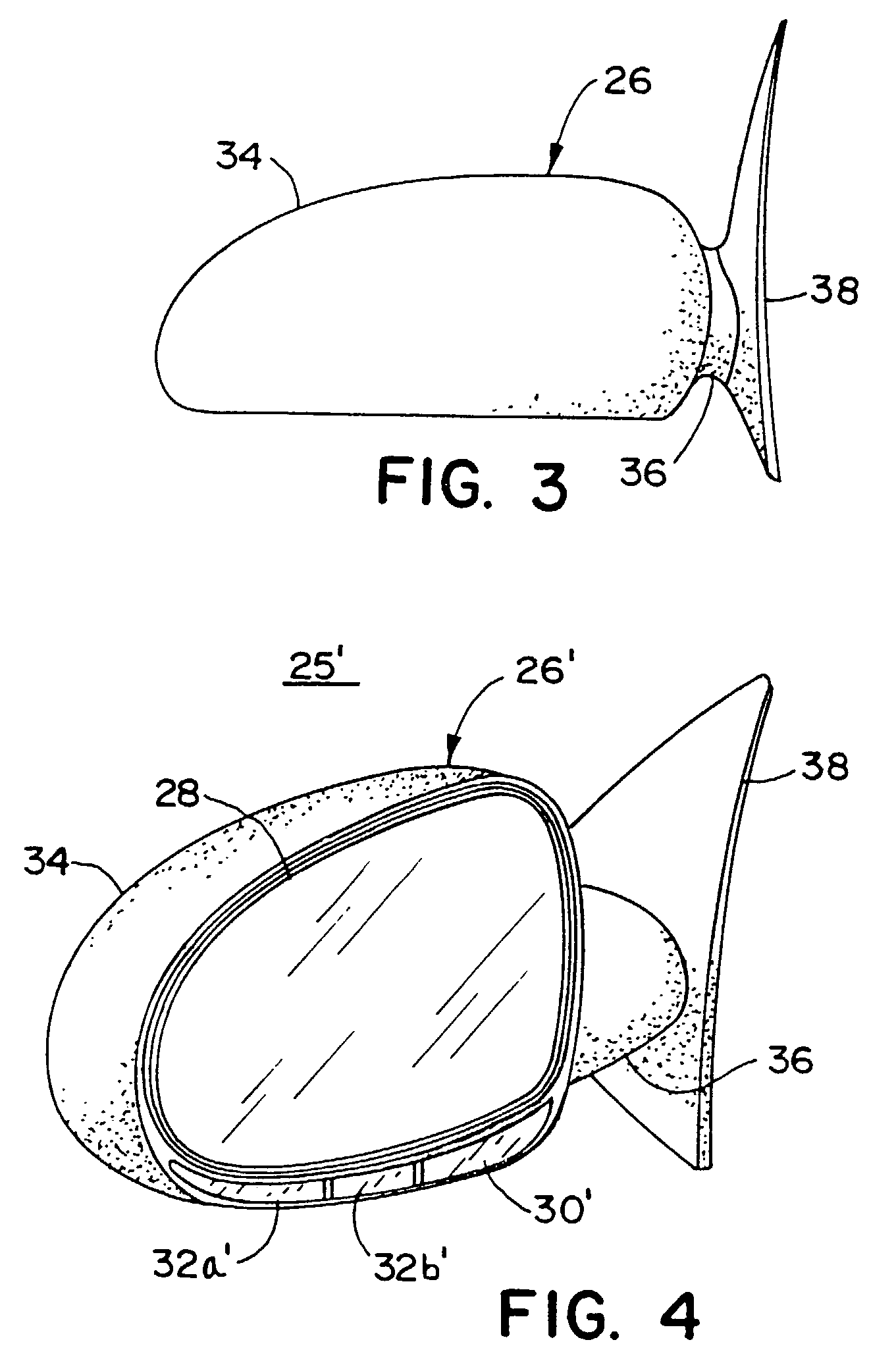
The present invention provides a personal safety feature for a vehicle in the form of a floodlight that can be positioned in the housing of an exterior mirror and projected downwardly and rearwardly on an area adjacent to the vehicle. The floodlight can be remotely actuated by a base unit and a remote transmitter, and its actuation is prevented when the vehicle is in motion. The floodlight creates a lighted security zone around the vehicle, providing a deterrent to ward off persons lurking around the vehicle. The invention also includes a signal light that provides a warning to approaching vehicles or those in the vehicle's blind spot. The signal light is designed to be observed by other vehicles but not directly by the driver of the vehicle. The invention further provides an exterior mirror system that incorporates a security light into the exterior rearview mirror assembly. The light pattern generated by the security light is restricted from direct observation by the driver of the vehicle. The invention also includes a powerfold exterior mirror system that includes a security light.

Problems solved by technology

In this manner, the pattern generated by the signal light cannot be substantially observed by a driver of the vehicle.

Method used


Image

  • Vehicle exterior mirror system with signal light
  • Vehicle exterior mirror system with signal light
  • Vehicle exterior mirror system with signal light

Examples


second embodiment

[0048]FIG. 27 is an elevation view of the exterior rearview mirror assembly of the present invention;

[0049]FIG. 28 is a bottom plan view of the exterior rearview mirror assembly of FIG. 27;

[0050]FIG. 29 is a plan view of a light module of the exterior rearview mirror assembly of FIG. 28;

third embodiment

[0051]FIG. 30 is a perspective view of the exterior rearview mirror assembly of the present invention;

[0052]FIG. 31 is an exploded perspective view of a signal light of FIG. 30;

[0053]FIG. 31A is a front elevation of a light source of the signal light of FIG. 31;

[0054]FIG. 31B is a side view of the light source of FIG. 31A;

[0055]FIG. 32A is a plan view of a second embodiment of the signal light of FIG. 31;

[0056]FIG. 32B is a plan view of a third embodiment of the signal light of FIG. 31;

fourth embodiment

[0057]FIG. 33 is a plan view of the exterior rearview mirror assembly of the present invention shown mounted to a vehicle;

[0058]FIG. 34 is an enlarged plan view of the exterior rearview mirror assembly of FIG. 33 illustrated in a normal extended position;

[0059]FIG. 35 is an enlarged plan view of the exterior mirror assembly of FIG. 33 in a folded position;

[0060]FIG. 36 is a cross-sectional view taken along line XXXVI—XXXVI of FIG. 34 illustrating a light module of the exterior rearview mirror assembly of FIG. 33 and a positioning mechanism for the light module;

[0061]FIG. 37 is an elevation view of one the exterior rearview mirror assemblies of FIG. 33; and


PUM


Abstract

An exterior mirror assembly for a vehicle includes a signal light that provides an advanced notification system to approaching vehicles that the driver of the vehicle intends to turn or make a lane change. The exterior mirror assembly includes a housing with a reflective element and a positioning device for adjusting the position of the reflective element in the housing, and at least one signal light positioned in the housing. The signal light includes a light source and a light conduiting member which is adapted to project a pattern of light from the housing and yet restrict light from extending into the vehicle so that a driver seated in the vehicle does not directly observe the pattern of light. The light source may be provided by a light pipe which is optically coupled to a remote light source located, for example, in the vehicle. Preferably, the pattern of light extends rearwardly, forwardly, and laterally from the vehicle. In one form, the light conduiting member includes a light input surface on one end and at least one light emitting surface for directing light outwardly from the housing of the exterior mirror assembly. In another form, the exterior mirror assembly incorporates a signal light which includes a plurality of reflective surfaces for directing light forwardly, rearwardly, and laterally from the vehicle but restricts light from entering into the vehicle and distracting the driver. In yet another form, the exterior mirror assembly includes a powerfold mirror system which incorporates a security light in either the folding portion or non-folding portion of the powerfold mirror system.

Description

[0001]This application is a divisional application of U.S. patent application Ser. No. 09 / 690,048, filed Oct. 16, 2000 now U.S. Pat. No.6,568,839, entitled VEHICLE EXTERIOR MIRROR SYSTEM WITH SIGNAL LIGHT, which is a divisional of U.S. patent application Ser. No. 09 / 102,414, filed on Jun. 22, 1998, now U.S. Pat. No. 6,176,602, which is a continuation-in-part of application Ser. No. 08 / 934,490, filed Sep. 19, 1997, now U.S. Pat. No. 5,863,116, which is a continuation of Pat. application Ser. No. 08 / 607,285, filed Feb. 26, 1996, now U.S. Pat No. 5,669,705, which is a continuation of patent application Ser. No. 08 / 333,412, filed Nov. 2, 1994, now U.S. Pat. No. 5,497,305, which is a continuation of patent application Ser. No. 08 / 011,947, filed Feb. 1, 1993, now Pat. No. 5,371,659, all of which are incorporated herein by reference in their entireties. The grandparent application, namely Ser. No. 09 / 102,414, filed Jun. 22, 1998, is additionally a continuation-in-part of patent application...

Claims


Application Information

Patent Timeline
Patent Type & Authority Patents(United States)
IPC IPC(8): B60Q1/26B60Q1/24B60R1/06G02B7/182B60Q1/12B60Q1/14B60R1/12B60R21/12
CPCB60Q1/2665B60R1/1207B60Q2900/30B60R2001/1284B60R21/12
Inventor PASTRICK, TODD WVAN DE VEN, MICHIEL PWHITEHEAD, PETER JMOUSSEAU, RICKLYNAM, NIALL R
Owner MAGNA MIRRORS OF AMERICA INC
Learn More