Intraocular pressure measurement system including a sensor mounted in a contact lens

a technology of intraocular pressure and sensor, which is applied in the field of system for measuring intraocular pressure in the eye, can solve the problems of patient resistance to compliance, patient's actual risk of blindness may be misdiagnosed, patient may be falsely diagnosed and be required to undergo therapy

Inactive Publication Date: 2007-01-30
THE CLEVELAND CLINIC FOUND
View PDF20 Cites 157 Cited by
  • Summary
  • Abstract
  • Description
  • Claims
  • Application Information

AI Technical Summary

Problems solved by technology

This becomes a nuisance to the patient after a time leading to patient resistance to compliance.
Therefore, if the pressure is normal at the time of the visit, but becomes high thereafter, the patient's actual risk of blindness may be misdiagnosed.
Also, if the pressure measured at the time of the office visit is high for reasons other than eye degeneration, the patient may be falsely diagnosed and be required to undergo therapy that may not be needed.
However, the device proposed is relatively large and bulky, about the size of an attache' case, for example, and not conducive to convenient transport with the patient during normal daily routine in order to measure IOP.
Also, very crude attempts have been made to develop methods of non

Method used


Image

  • Intraocular pressure measurement system including a sensor mounted in a contact lens
  • Intraocular pressure measurement system including a sensor mounted in a contact lens
  • Intraocular pressure measurement system including a sensor mounted in a contact lens

Examples


Embodiment Construction

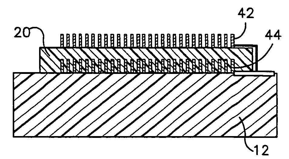
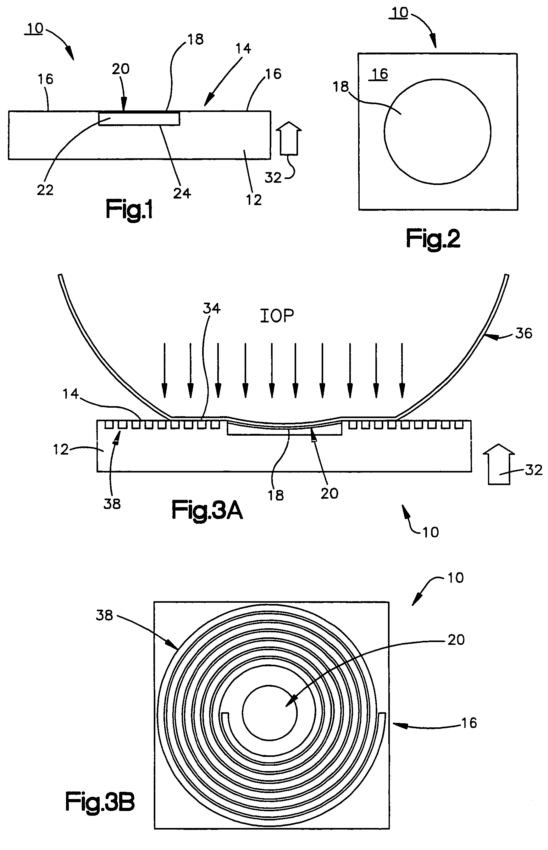
[0029]A tonometer sensor 10 produced using microelectromechanical system (MEMS) techniques is shown in FIGS. 1 and 2. The tonometer sensor 10 includes a substrate 12 that is comprised of a silicon material, but it should be understood that other materials may be used. The substrate 12 includes a contact surface 14 for making contact with a surface portion 34 (FIG. 3A) of an eye 36. The contact surface 14 includes an outer non-compliant region 16 (FIG. 1) and an inner compliant region 18 that is fabricated using MEMS techniques (which will be described in greater detail herein below) as an impedance element, the impedance of which varies as the inner compliant region 18 changes shape. The compliant region 18 comprises a diaphragm 20 as one plate of a capacitive element that is separated by a dielectric 22 from another plate 24 of the capacitive element which is part of the non-compliant region 16. As will become more evident from the description below, as the contact surface 14 is pr...


PUM


Abstract

An apparatus (180) for measuring intraocular pressure (IOP) comprises a contact lens (40) including an inner surface (42) contoured to a surface portion (34) of an eye (36) and a sensor (10) disposed in the contact lens. The sensor (10) comprises a contact surface (14) for making contact with the surface portion (34) of the eye (36). The contact surface (14) includes an outer non-compliant region (16) and an inner compliant region (18) fabricated as an impedance element that varies in impedance as the inner compliant region changes shape. The sensor (10) further comprises a region of conductive material (38) electrically coupled to the impedance element of the compliant region (18) and responsive to an external signal for energizing the impedance element so that the IOP may be determined.

Description

RELATED APPLICATIONS[0001]This application is a continuation of co-pending U.S. patent application Ser. No. 10 / 128,321, filed Apr. 22, 2002, entitled “MEASUREMENT SYSTEM INCLUDING A SENSOR MOUNTED IN A CONTACT LENS” (now U.S. Pat. No. 6,749,568), which is a continuation-in-part of a co-pending U.S. patent application Ser. No. 09 / 642,573, entitled “SYSTEM FOR MEASURING INTRAOCULAR PRESSURE FOR AN EYE AND A MEM SENSOR FOR USE THEREWITH”, filed Aug. 21, 2000 (now U.S. Pat. No. 6,447,449). The subject matter of the aforementioned co-pending application is incorporated herein by reference.FIELD OF THE INVENTION[0002]The present invention relates to a system for measuring intraocular pressure (IOP) in an eye, and is particularly directed to a system for measuring IOP that utilizes a sensor fabricated through microelectromechanical system (MEMS) technology and which is mounted in a contact lens.BACKGROUND OF THE INVENTION[0003]Glaucoma patients and post-operative patients of eye surgery re...

Claims


Application Information

Patent Timeline
IPC IPC(8): A61B3/16A61B5/00
CPCA61B3/16A61B2562/028
Inventor FLEISCHMAN, AARON J.ROY, SHUVOLEWIS, HILEL
Owner THE CLEVELAND CLINIC FOUND
Why Eureka
Try Eureka