Reinforced retention structures

Inactive Publication Date: 2007-01-30
BOSTON SCI SCIMED INC
View PDF69 Cites 14 Cited by
  • Summary
  • Abstract
  • Description
  • Claims
  • Application Information

AI Technical Summary

Benefits of technology

[0005]Known anchoring mechanisms used with medical devices can fail. For example, internal forces from involuntary bodily functions (such as peristalsis and other secretory forces, as well as patient movement) can force the device out of its intended position within the body. In addition, doctors typically recommend catheter and stent anchoring or

Problems solved by technology

Known anchoring mechanisms used with medical devices can fail.
Also, the lower strengths of these softer materials

Method used


Image

  • Reinforced retention structures
  • Reinforced retention structures
  • Reinforced retention structures

Examples


Example

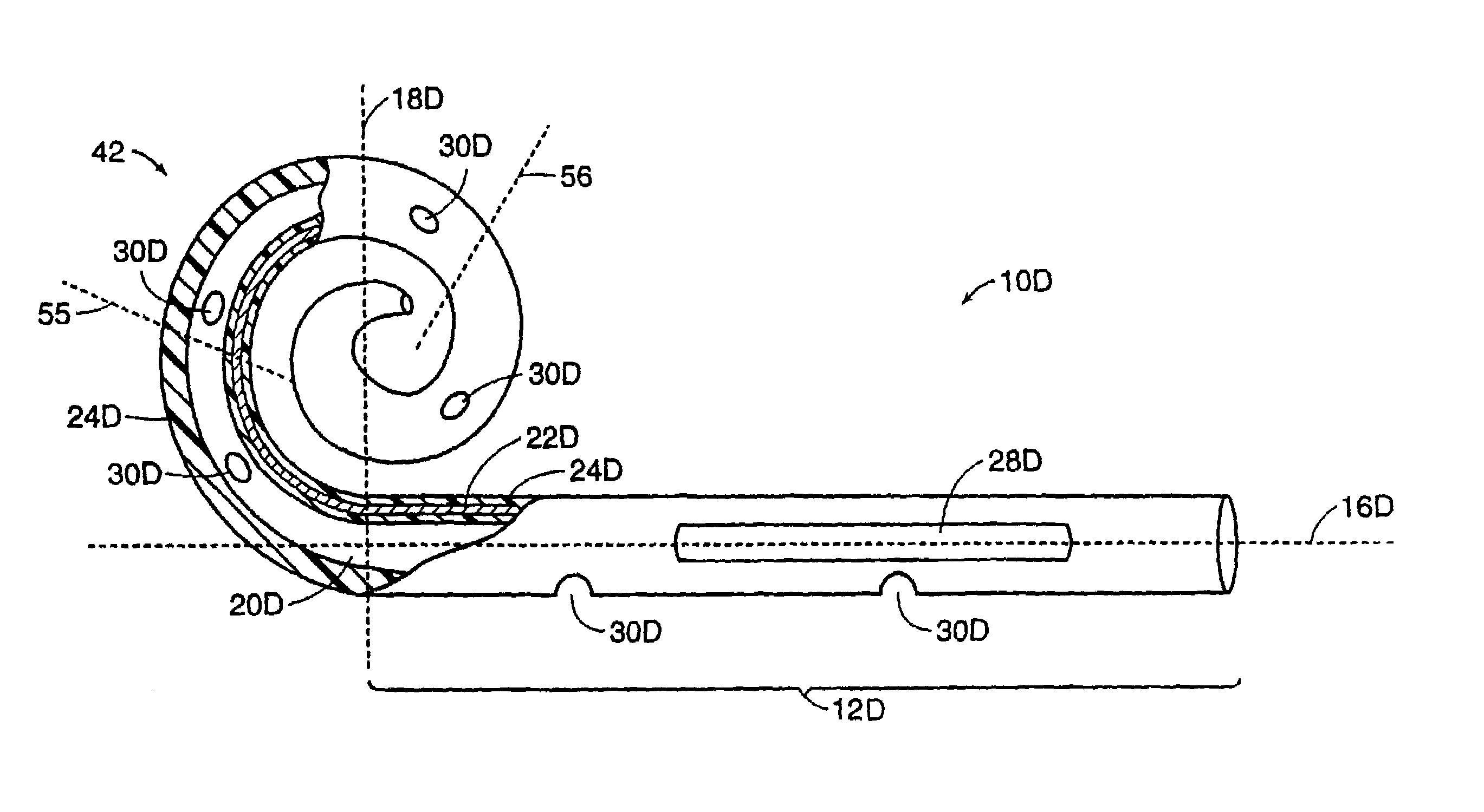
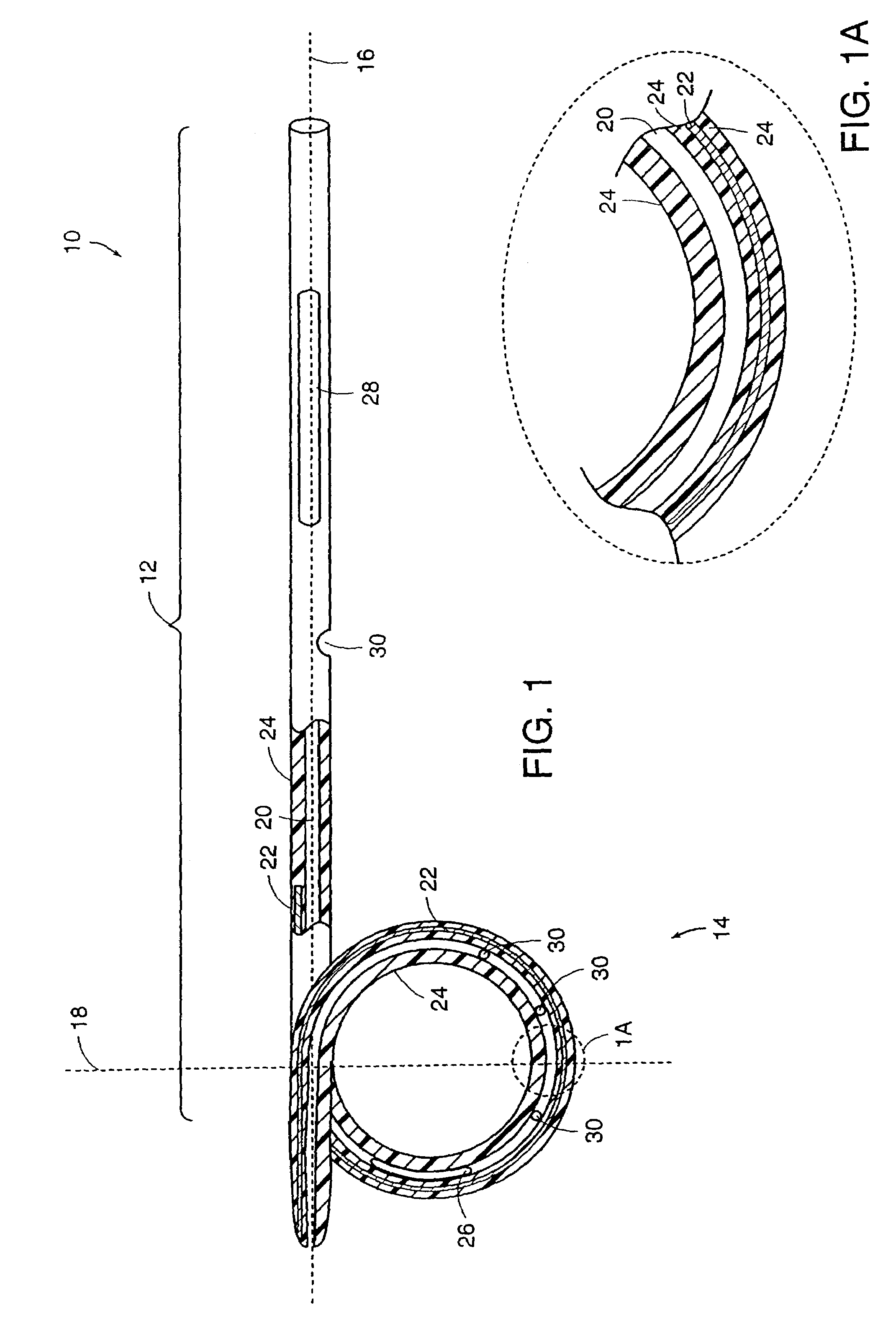
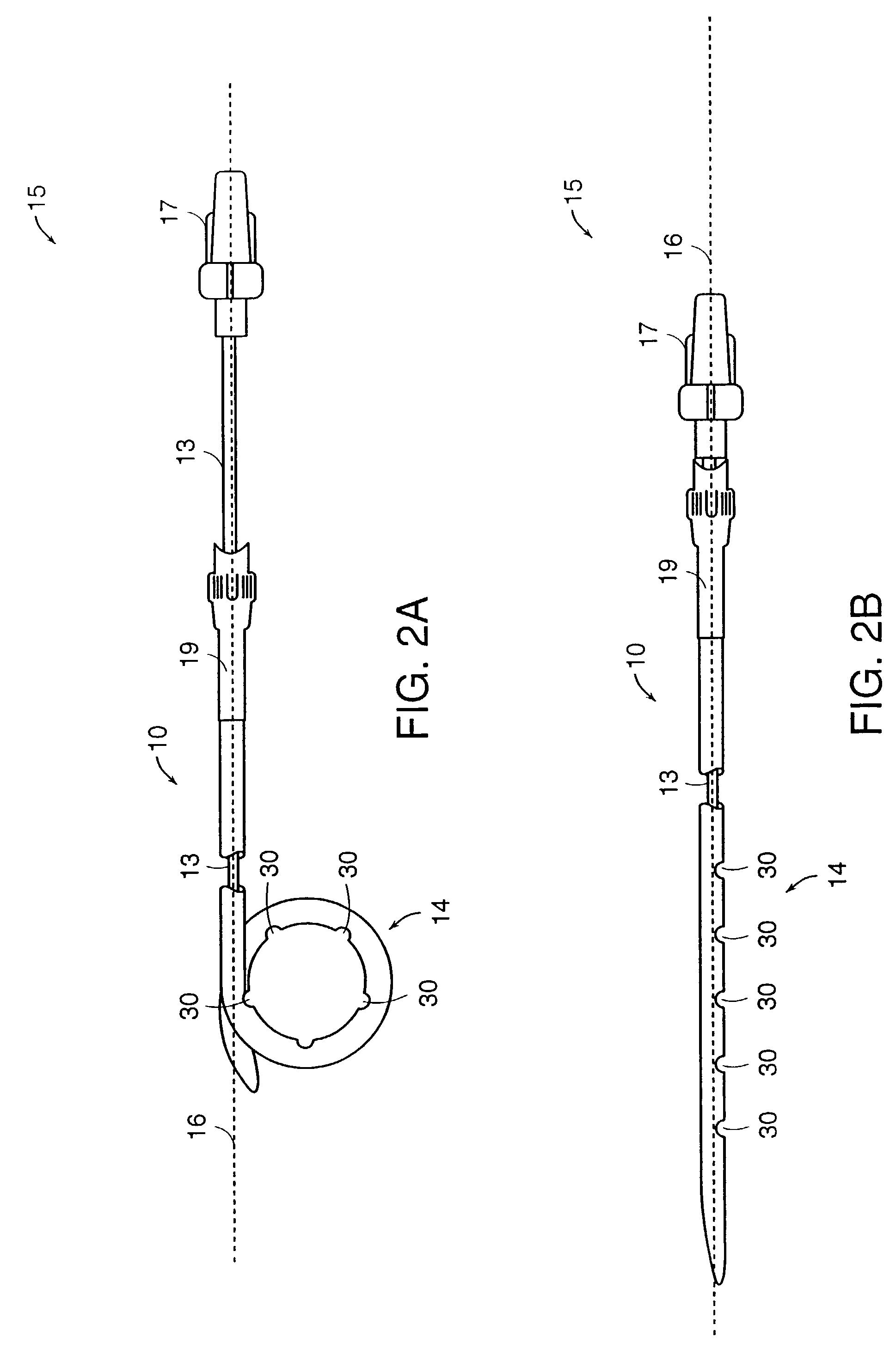
[0034]Medical devices of the present invention are generally constructed of an elongated member and a reinforced retention structure. The elongated member includes a flexible material and the reinforced retention structure includes the same or a different flexible material with an elastic member embedded within or bound to a surface or groove of the flexible material. Preferred materials for the flexible material include, but are not limited to plastic, silicone, TEFLON® and other PTFE polymers, polyurethane polymers and the like. These materials may also be provided with radiopaque portions to assist in the implantation of the devices in a body of a patient under fluoroscopic monitoring.

[0035]The elongated member may be tubular or conical or a combination of both. Generally, the elongated member comprises a lumen extending through the entire length of the elongated member to provide drainage of fluid from a body cavity. Alternatively or additionally, drainage may be provided or enh...


PUM


Abstract

A medical device includes an elongated member and a reinforced retention structure. The device can be used for draining substances from organs or abscessed areas within a body of a patient. The elongated member is made of a flexible material. The reinforced retention structure extends from or is formed integrally with the elongated member and comprises an elastic member and the flexible material. The reinforced retention structure provides retention strength while providing flexibility and patient comfort. The use of the reinforced retention structure also provides increased stability to the device within the patient's body and combats migration and/or expulsion of the device. The nature of the reinforcement in the retention structure may extend into the elongated member, which allows for larger drainage openings in the device and increases the radiopacity of the device.

Description

RELATED APPLICATIONS[0001]This application is a continuation of U.S. Ser. No. 09 / 829,705, filed Apr. 10, 2001 now U.S. Pat. No. 6,569,150, which claims the benefit of U.S. Provisional Application No. 60 / 195,995, filed Apr. 11, 2000. The entire disclosure of both of these applications is incorporated by reference herein.TECHNICAL FIELD[0002]This invention generally relates to medical devices, such as drainage stents and catheters.BACKGROUND INFORMATION[0003]Medical devices used for draining fluids from body cavities are generally made of plastic tubing. The tubing is often pre-formed on one or both of its ends to a geometry designed to maintain or anchor the device in position within the body. Medical devices of this type are commonly placed through a ureteroscope, laprascope, or endoscope and into lumens and / or body orifices. In the case of abscess catheters, placement generally occurs percutaneously through a puncture of the external dermis and musculature. In most cases, however, ...

Claims


Application Information

Patent Timeline
IPC IPC(8): A61M25/00A61M25/04A61M25/16
CPCA61M25/04A61M27/008A61M27/002A61M2210/1078
Inventor TEAGUE, JAMES A.BOTTCHER, BENJAMIN
Owner BOSTON SCI SCIMED INC
Why Eureka
Try Eureka