Electronic ballast and method for driving fluorescent lamp

Inactive Publication Date: 2008-02-28
BEYOND INNOVATION TECH
View PDF2 Cites 0 Cited by
  • Summary
  • Abstract
  • Description
  • Claims
  • Application Information

AI Technical Summary

Benefits of technology

[0011]Accordingly, at least one objective of the present invention is to provide an electronic ballast for driving a fluorescent lamp c

Problems solved by technology

In very early days, light was a very important issue in our everyday life.
As a result of the sudden inrush of a large current, the devices inside the electronic ballast easily burnout.
Moreover, a large number of lamp tubes are being installed inside most buildings.
Using a

Method used


Image

  • Electronic ballast and method for driving fluorescent lamp
  • Electronic ballast and method for driving fluorescent lamp
  • Electronic ballast and method for driving fluorescent lamp

Examples


Example

[0024]Reference will now be made in detail to the present preferred embodiments of the invention, examples of which are illustrated in the accompanying drawings. Wherever possible, the same reference numbers are used in the drawings and the description to refer to the same or like parts.

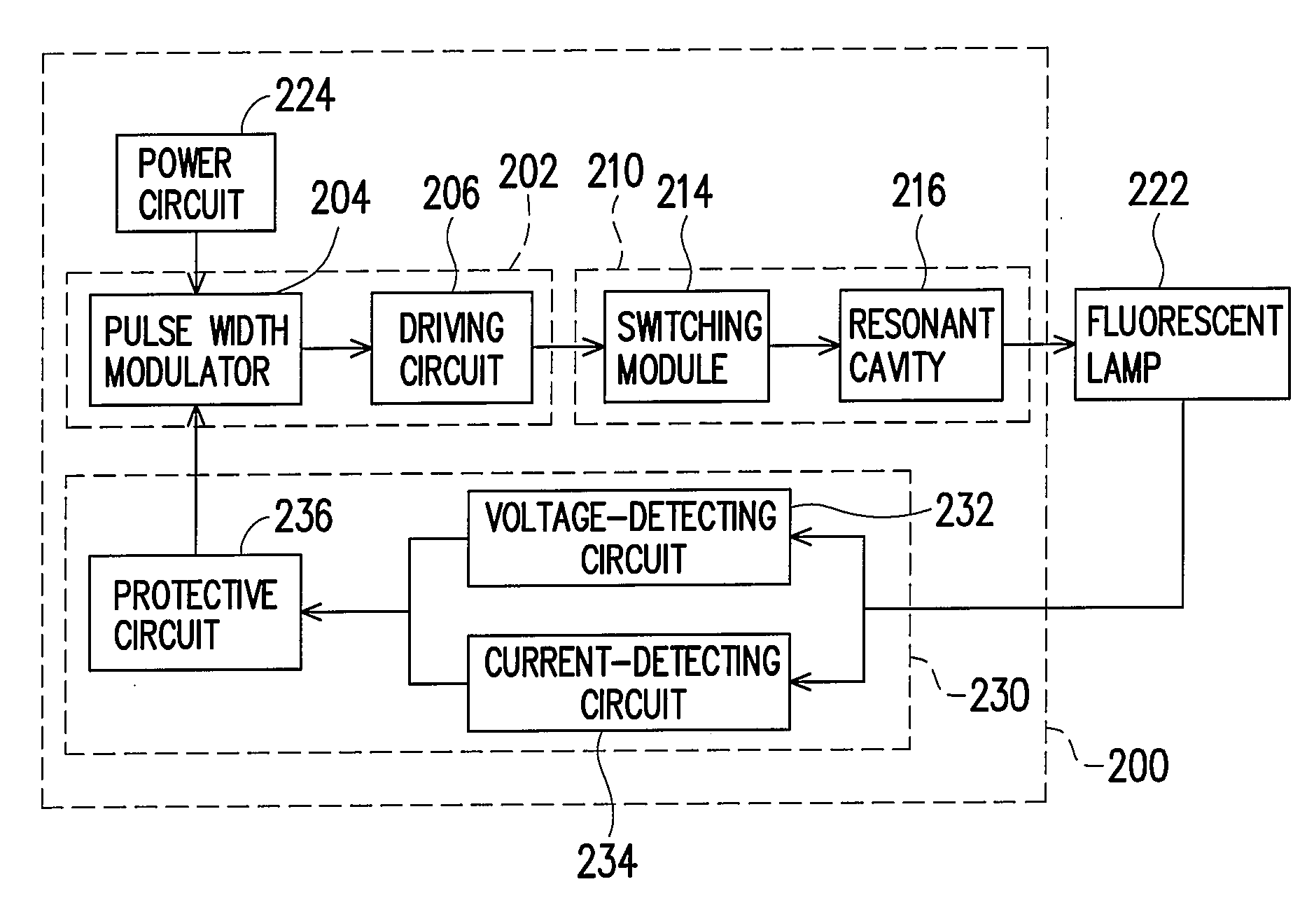
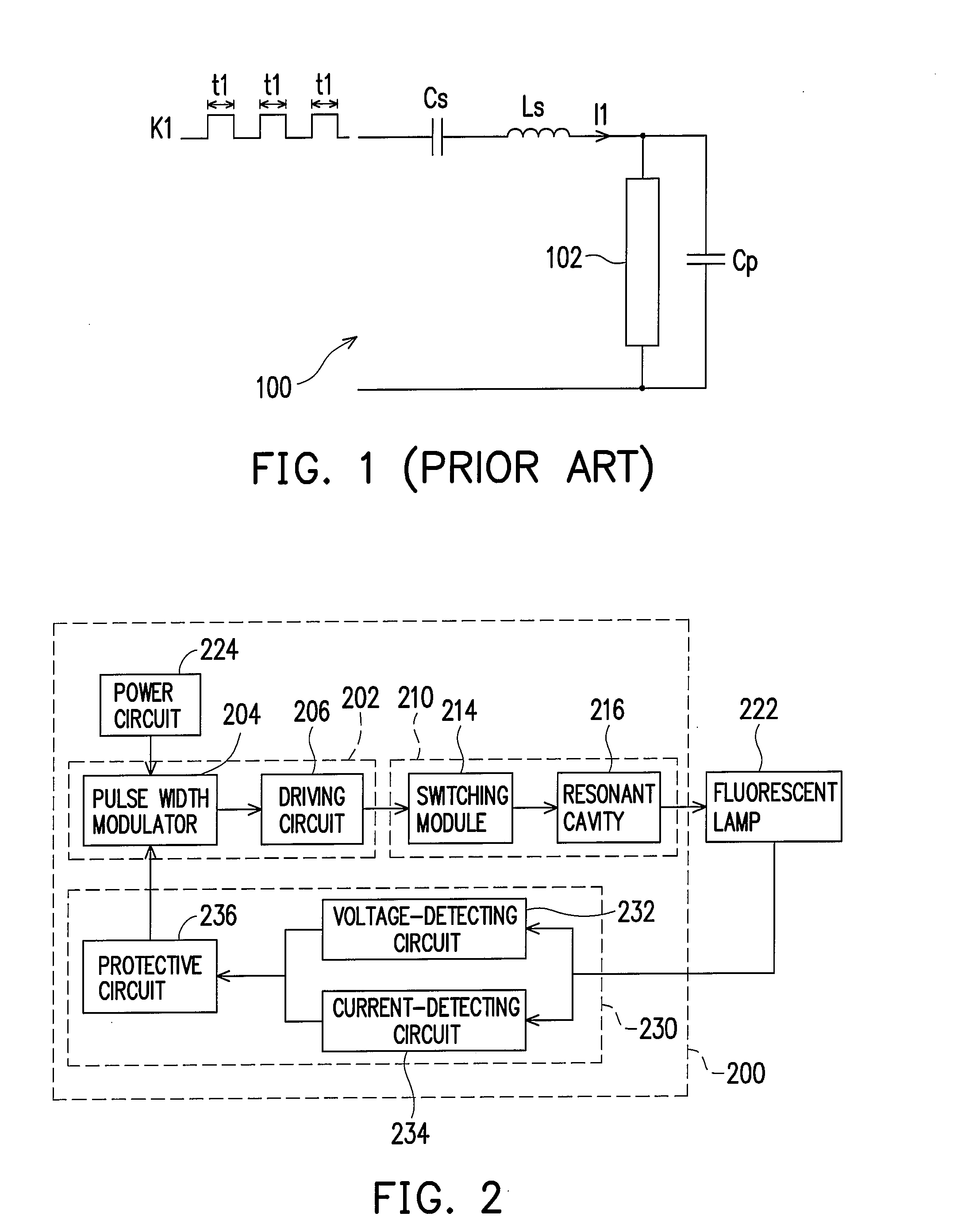
[0025]FIG. 2 is a circuit block diagram of an electronic ballast according to one preferred embodiment of the present invention. As shown in FIG. 2, the electronic ballast 200 in the present embodiment is used for driving a fluorescent lamp. The electronic ballast 200 includes a pulse width modulation (PWM) unit 202 and a power-converting unit 210. In the present embodiment, the duty cycle of the PWM signal generated by the PWM unit 202 is varied with time when the fluorescent lamp is in a pre-heating period.

[0026]The PWM unit 202 has a pulse width modulator 204 and a driving circuit 206. The pulse width modulator 204 is used for generating a PWM signal. The driving circuit 206 amplifies the PWM sign...


PUM


Abstract

An electronic ballast comprising a pulse width modulation (PWM) unit and a power-converting unit is provided. The PWM unit is used for generating a PWM signal to the power-converting unit so that the power-converting unit can generate a driving signal to drive and light up the fluorescent lamp according to the PWM signal. Specially, the duty cycle of the PWM signal is varied with time in a pre-heating period of the fluorescent lamp. In addition, the present invention further includes a detecting module for detecting a working voltage and a working current of the fluorescent lamp to determine whether the fluorescent lamp works normally. When the fluorescent lamp cannot work normally, the PWM signal generated by the PWM unit is disabled through the detecting module.

Description

CROSS-REFERENCE TO RELATED APPLICATION[0001]This application claims the priority benefit of Taiwan application serial no. 95130782, filed Aug. 22, 2006. All disclosure of the Taiwan application is incorporated herein by reference.BACKGROUND OF THE INVENTION[0002]1. Field of the Invention[0003]The present invention relates to an electronic ballast, and more particularly, to an electronic ballast that uses a pulse width modulation (PWM) signal with variable duty cycle to drive a fluorescent lamp.[0004]2. Description of Related Art[0005]In very early days, light was a very important issue in our everyday life. After Thomas Edison invented the electric light bulb, lighting equipment has evolved one big step ahead into a new milestone. At present, a variety of different light sources, from small semiconductor light-emitting diodes to big neon signs lining major streets of our big cities, are available. All these light sources also add considerable colors to this world.[0006]Among the thr...

Claims


Application Information

Patent Timeline
IPC IPC(8): H05B41/36
CPCH05B41/2981
Inventor LEE, CHIH-SHUN
Owner BEYOND INNOVATION TECH
Why Eureka
Try Eureka