Method and apparatus for the automatic determination of network cable connections using RFID tags and an antenna grid

a network cable connection and automatic determination technology, applied in the field of radio frequency identification (rfid) systems, can solve the problems of prohibitively expensive, rfid readers are typically not so inexpensive, etc., and achieve the effect of convenient and efficient determination

Inactive Publication Date: 2007-01-30
RPX CORP +1
View PDF10 Cites 148 Cited by
  • Summary
  • Abstract
  • Description
  • Claims
  • Application Information

AI Technical Summary

Benefits of technology

[0009]Thus, according to the principles of the present invention, when RFID tags have been fixed to one or more cable ends, it can advantageously be determined which of the one or more cables are connected to which of the ports on the device. In accordance with one illustrative embodiment of the present invention, the RF antenna grid comprises a plurality of individual antennas which are advantageously multiplexed such that a single RFID reader can handle the sensing for all antennas. Also, in accordance with one illustrative embodiment of the present invention, the opposing ends of a given cable are advantageously provided with RFID tags having related ID codes such that connections which exist between two connected ports of the device may be easily and efficiently determined.

Problems solved by technology

This, however, might be prohibitively expensive.
(As is familiar to those of ordinary skill in the art, whereas RFID tags are extremely inexpensive, RFID readers are typically not so inexpensive.)

Method used


Image

  • Method and apparatus for the automatic determination of network cable connections using RFID tags and an antenna grid
  • Method and apparatus for the automatic determination of network cable connections using RFID tags and an antenna grid
  • Method and apparatus for the automatic determination of network cable connections using RFID tags and an antenna grid

Examples


Embodiment Construction

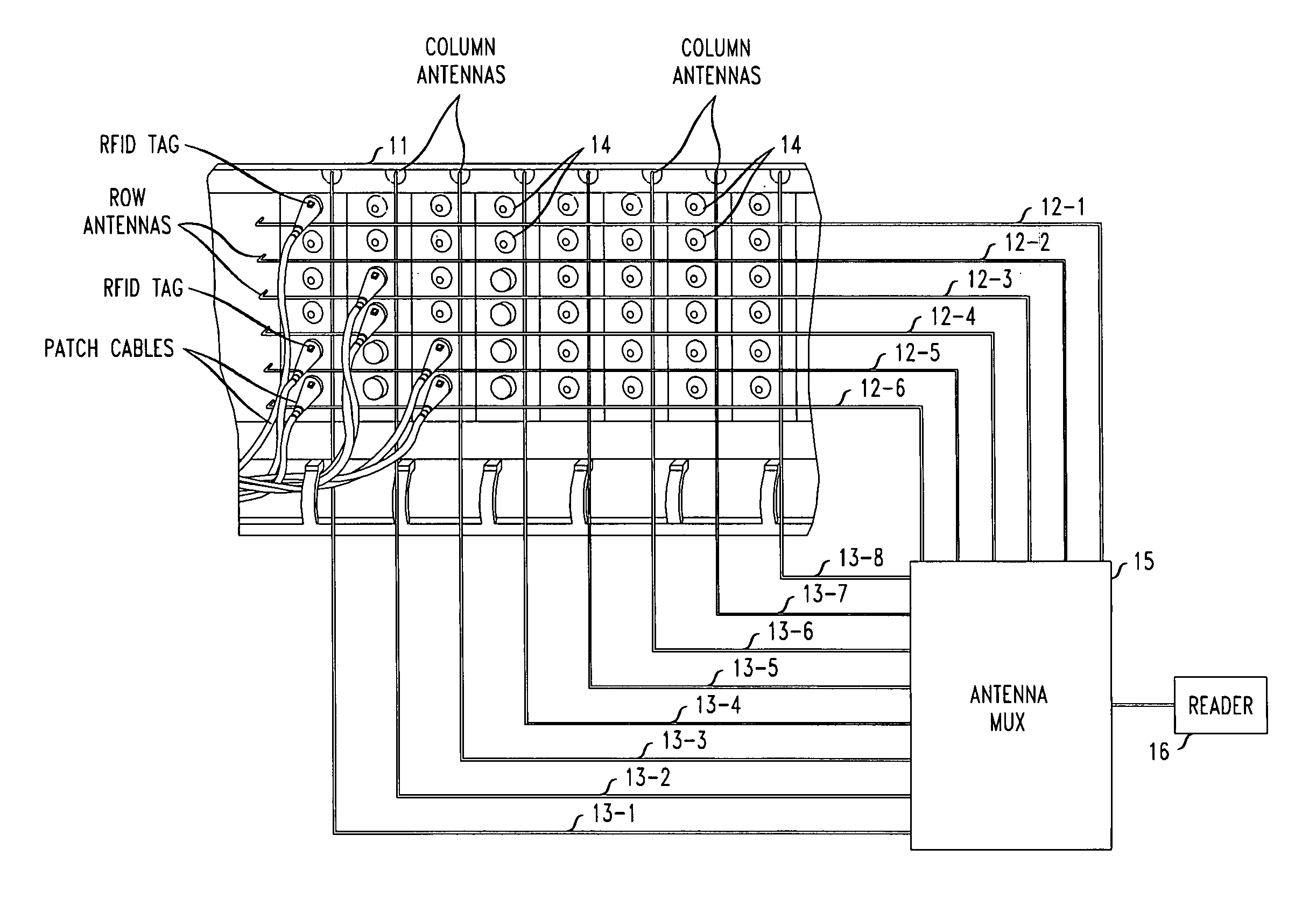
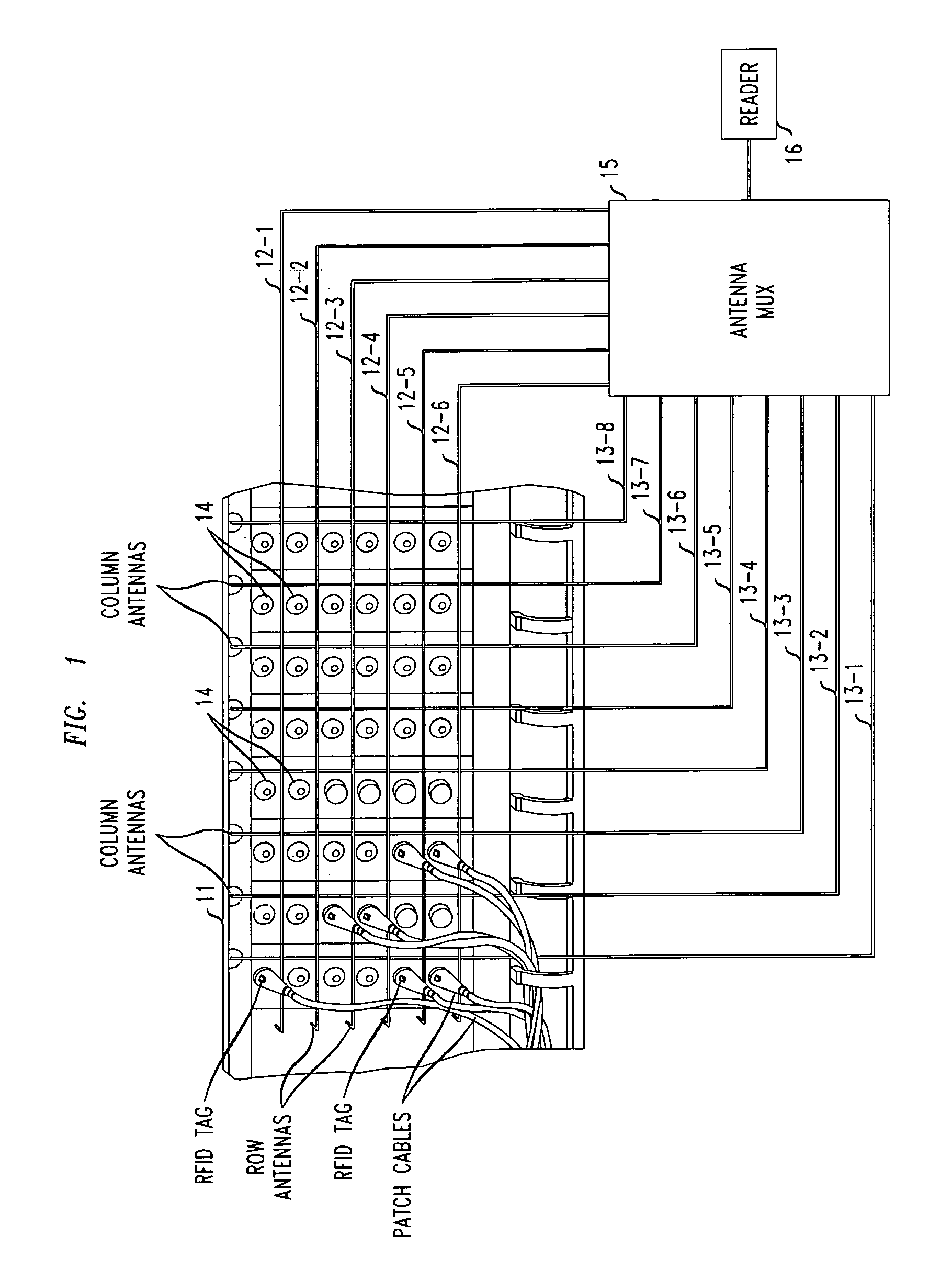
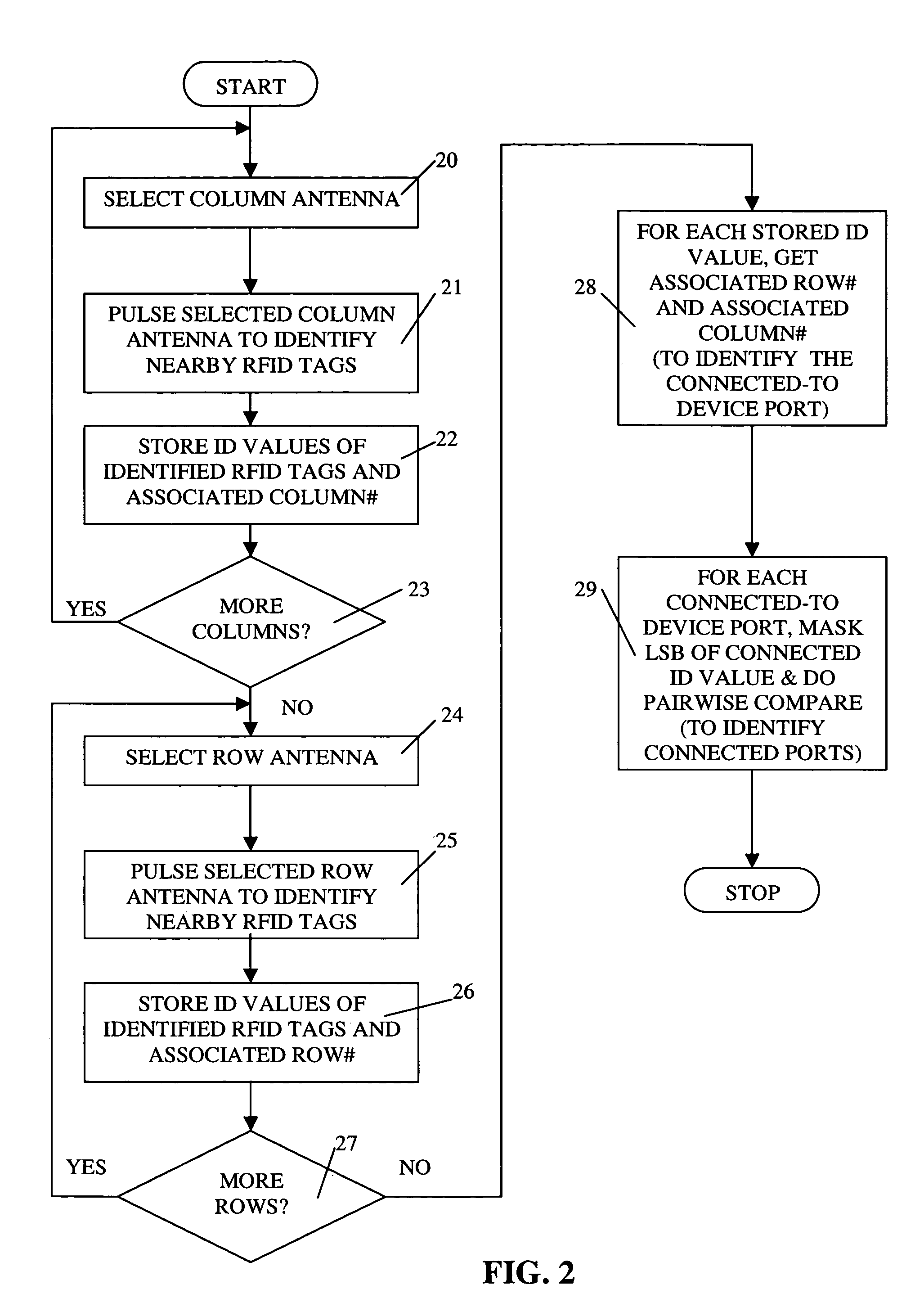
[0012]In accordance with one illustrative embodiment of the present invention, RFID techniques are advantageously employed to automatically determine the connection between one or more network cables and a plurality of device ports on a patch panel of a given piece of equipment. Illustratively, the given piece of equipment may comprise a telecommunications switch and the cables may comprise telecommunications network cables.

[0013]More specifically, in accordance with the (preferred) illustrative embodiment of the invention, each of the network cables which may be connected to one of the device ports is advantageously marked—preferably at each end thereof—with an RFID device (i.e., an RFID “tag”). In particular, each end of each cable comprises an RFID tag having a unique ID value. As is well known to those of ordinary skill in the art, each RFID tag in an RFID system has a typically unique identification code (referred to herein as an “ID value”) so that its presence near an RFID se...


PUM


Abstract

Radio Frequency Identification (RFID) tags and an antenna grid are used for automatic determination of cable connections. An RF antenna grid is advantageously employed on a device having a plurality of device ports (e.g., cable connection points) which may, for example, be physically organized in a two-dimensional arrangement. Then, when RFID tags are fixed to one or more cable ends, it can advantageously be determined which of the one or more cables are connected to which of the ports on the device. The RF antenna grid may comprise a plurality of individual antennas which are advantageously multiplexed such that a single RFID reader can handle the sensing for all antennas. Also, opposing ends of a given cable may be advantageously provided with RFID tags having related ID codes such that connections which exist between two connected ports of the device may be easily and efficiently determined.

Description

FIELD OF THE INVENTION[0001]The present invention relates generally to the field of Radio Frequency Identification (RFID) systems and more particularly to the use of RFID techniques for the automatic determination of network cable connections.BACKGROUND OF THE INVENTION[0002]The management of complicated networks such as telecommunications networks or sophisticated computer networks is tremendously expensive. A substantial portion of this cost arises from incomplete, incorrect or ambiguous knowledge about a network. For example, a telecommunications network operator may not have an accurate record of how network switches are configured, leading to failed attempts to fix problems or provision new services. This lack of knowledge can in some instances be remedied by polling the networking equipment to determine its actual settings.[0003]However, a more fundamental ambiguity arises at the physical level of network cable management. Network cables may be added, removed or moved by suppo...

Claims


Application Information

Patent Timeline
Patent Type & Authority Patents(United States)
IPC IPC(8): H04Q5/22G06F19/00G06K7/00G01R31/02G01R31/04G08B13/14
CPCG01R31/023G06K7/10079G01R31/041G01R31/60G01R31/67
Inventor MARTIN, CLIFFORD E
Owner RPX CORP
Why Eureka
Try Eureka