Method and apparatus for indicating a usage context of a computational resource through visual effects

a technology of visual effects and computational resources, applied in the field of user interfaces for computer systems, can solve the problems of little attention to supporting existing, legacy window-based 2d applications within these 3d user interfaces, and achieve the effect of facilitating the use of visual effects

Active Publication Date: 2007-01-30
ORACLE INT CORP
View PDF21 Cites 98 Cited by
  • Summary
  • Abstract
  • Description
  • Claims
  • Application Information

AI Technical Summary

Benefits of technology

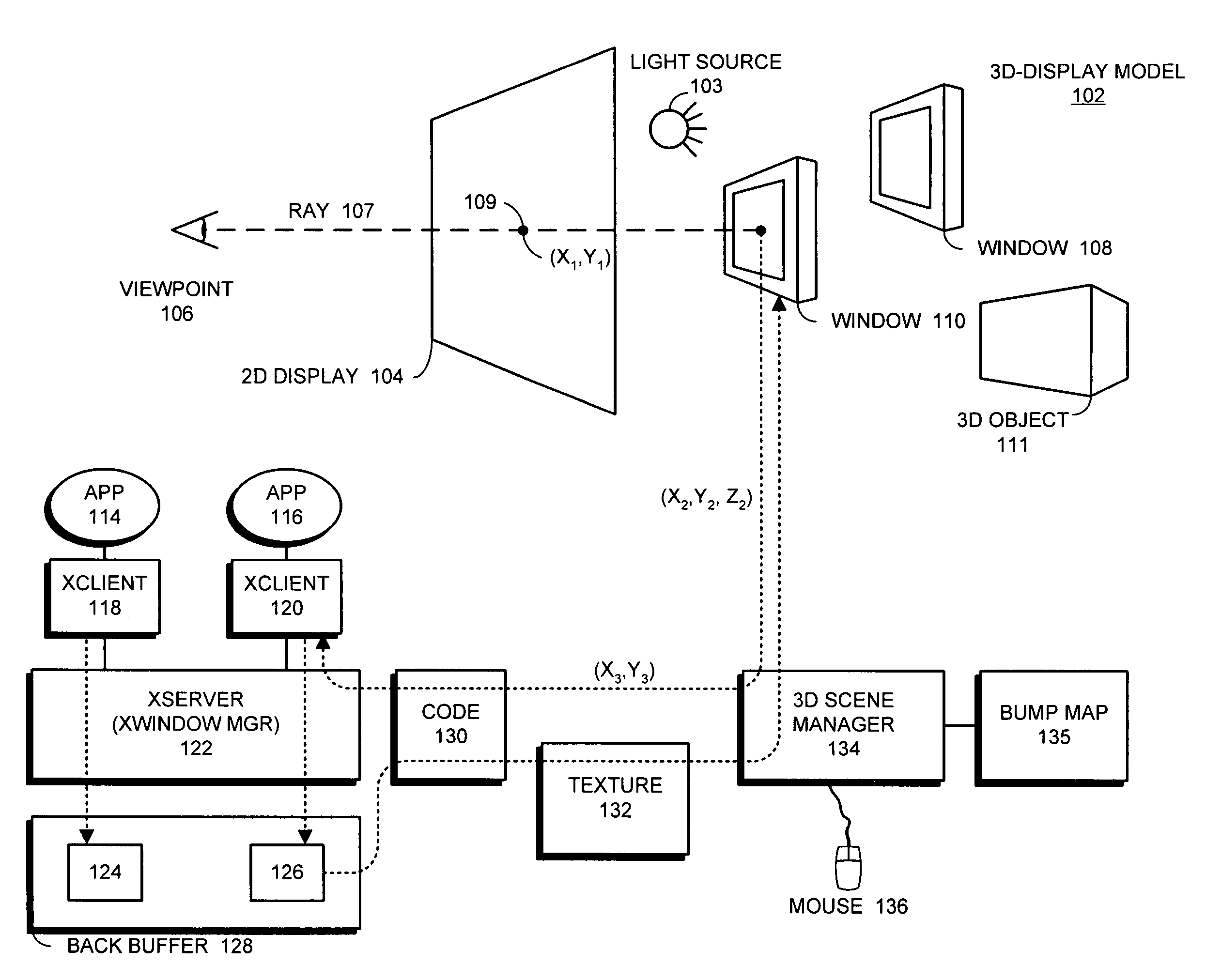
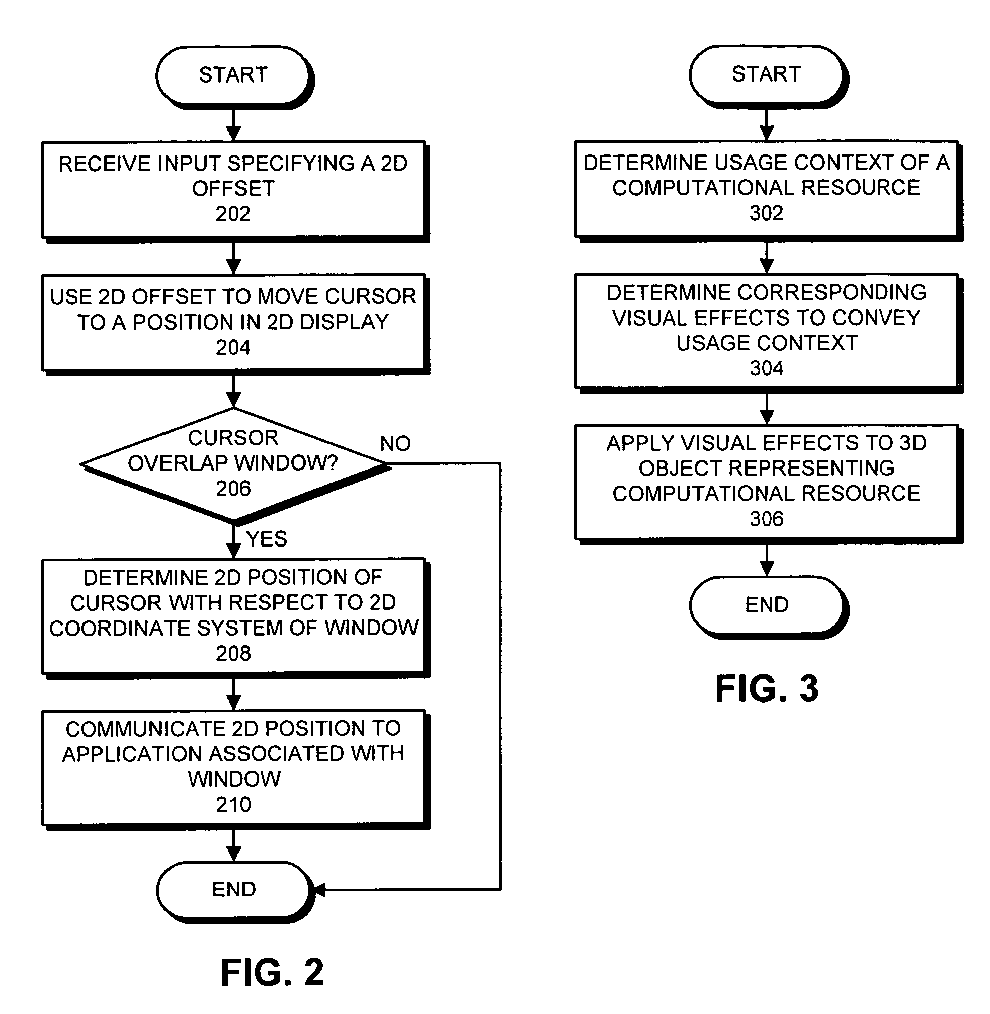
[0009]One embodiment of the present invention provides a system that facilitates using visual effects within a three-dimensional (3D) display environment to indicate a usage context of a computational resource, which is represented by a 3D object in the 3D display environment. During operation, the system determines the usage context of the computational resource. Next, the system determines visual effects corresponding to the usage context to apply to the 3D object which represents the computational resource. Finally, the system applies the visual effects to the 3D object. In this way, the usage context of the corresponding computational resource can be determined by viewing the 3D object within the 3D display environment.
[0012]In a variation on this embodiment, the visual effects can include a location of the 3D object, an orientation of the 3D object, a color of the 3D object, a texture of the 3D object, a surface pattern on the 3D object, a bump map for the 3D object, a size of the 3D object, lighting for the 3D object, transparency of the 3D object, reflectiveness of the 3D object, and simulated degradation of the 3D object.

Problems solved by technology

However, because of limitations on graphical processing power at the time windows were being developed, many of the design decisions for windows were made with computational efficiency in mind.
However, these 3D interfaces are mainly focused on exploiting 3D capabilities, while little attention has been given to supporting existing, legacy window-based 2D applications within these 3D user interfaces.

Method used


Image

  • Method and apparatus for indicating a usage context of a computational resource through visual effects
  • Method and apparatus for indicating a usage context of a computational resource through visual effects
  • Method and apparatus for indicating a usage context of a computational resource through visual effects

Examples


Embodiment Construction

[0030]The following description is presented to enable any person skilled in the art to make and use the invention, and is provided in the context of a particular application and its requirements. Various modifications to the disclosed embodiments will be readily apparent to those skilled in the art, and the general principles defined herein may be applied to other embodiments and applications without departing from the spirit and scope of the present invention. Thus, the present invention is not intended to be limited to the embodiments shown, but is to be accorded the widest scope consistent with the principles and features disclosed herein.

[0031]The data structures and code described in this detailed description are typically stored on a computer readable storage medium, which may be any device or medium that can store code and / or data for use by a computer system. This includes, but is not limited to, magnetic and optical storage devices such as disk drives, magnetic tape, CDs (...


PUM


Abstract

One embodiment of the present invention provides a system that facilitates using visual effects within a three-dimensional (3D) display environment to indicate a usage context of a computational resource, which is represented by a 3D object in the 3D display environment. During operation, the system determines the usage context of the computational resource. Next, the system determines visual effects corresponding to the usage context to apply to the 3D object which represents the computational resource. Finally, the system applies the visual effects to the 3D object. In this way, the usage context of the corresponding computational resource can be determined by viewing the 3D object within the 3D display environment.

Description

RELATED APPLICATION[0001]The subject matter of this application is related to the subject matter in a co-pending non-provisional application entitled, “Method and Apparatus for Manipulating Two-Dimensional Windows Within a Three-Dimensional Display Model,” by inventor Hideya Kawahara having Ser. No. 10 / 663,609, and filing date 15 Sep. 2003.BACKGROUND[0002]1. Field of the Invention[0003]The present invention relates to user interfaces for computer systems. More specifically, the present invention relates to a method and an apparatus for using visual effects to convey a usage context of a computational resource.[0004]2. Related Art[0005]Today, most personal computers and other high-end devices support window-based graphical user interfaces (GUIs), which were originally developed back in the 1980's. These window-based interfaces allow a user to manipulate windows through a pointing device (such as a mouse), in much the same way that pages can be manipulated on a desktop. However, becau...

Claims


Application Information

Patent Timeline
Patent Type & Authority Patents(United States)
IPC IPC(8): G06T15/00G06F3/033G06F3/048G06T15/20
CPCG06F3/04815G06T19/20G06F2203/04802G06T2219/2016G06T2219/2012G06T2200/24
Inventor KAWAHARA, HIDEYAROSE, CHESTER D.
Owner ORACLE INT CORP
Why Eureka
Try Eureka