Supercharge Your Innovation With Domain-Expert AI Agents!

Lifetime improvement in microstructures with deformable elements

a technology of deformation and life-long improvement, applied in the field of microstructures, can solve the problems of residual plastic deformation at the natural resting state, device failure of microstructures such as microelectromechanical devices, mems devices, etc., and achieve the effect of increasing the life of the devi

Active Publication Date: 2007-01-30
TEXAS INSTR INC
View PDF3 Cites 1 Cited by
  • Summary
  • Abstract
  • Description
  • Claims
  • Application Information

AI Technical Summary

Benefits of technology

The present invention provides a method for improving the lifetime of MEMS devices with deformable elements by illuminating them prior to delivery to customers. The illumination can be performed by exposing the device to an illumination light with a specific energy density for a specific duration of time. The illumination light can be generated by a microwave powered lamp or an arc lamp. The device can be exposed to the illumination light in many ways, such as by direct or indirect exposure. The method can be performed after the device is delivered to customers or during packaging. The illumination treatment can be performed at different time intervals and for multiple times. The invention provides a way to protect the deformable elements of MEMS devices from damage and improve their performance.

Problems solved by technology

Microstructures such as microelectromechanical devices (hereafter MEMS devices) having deformable elements may suffer from device failure when the deformable elements deform plastically.
Plastic deformation may be accumulated over operation time and result in residual plastic deformation at the natural resting state.
The residual plastic deformation alters the operational states of the MEMS device—causing device failure.
When such MEMS device is a member of an array of MEMS devices, the MEMS device may fail when one or more deformable elements of the MEMS devices in the array have residual plastic deformation more than a certain amount relative to the deformable elements of other MEMS devices in the array.
Such accumulated residual deformation, in turn, may alter an operation state, such as the natural resting state of the mirror plate, the OFF state, and / or the ON state, and may cause device failure when such alteration exceeds a certain amount.
When one or more of the deformable hinges of the micromirror devices in the array have residual plastic deformation exceeding beyond a certain amount relative to the deformable hinges of other micromirror devices, the micromirror array device, i.e. the spatial light modulator fails.
Illumination of the deformable hinges in the spatial light modulator may accelerate the plastic deformation, which in turn, reduces the lifetime of the device.

Method used


Image

  • Lifetime improvement in microstructures with deformable elements
  • Lifetime improvement in microstructures with deformable elements
  • Lifetime improvement in microstructures with deformable elements

Examples


Embodiment Construction

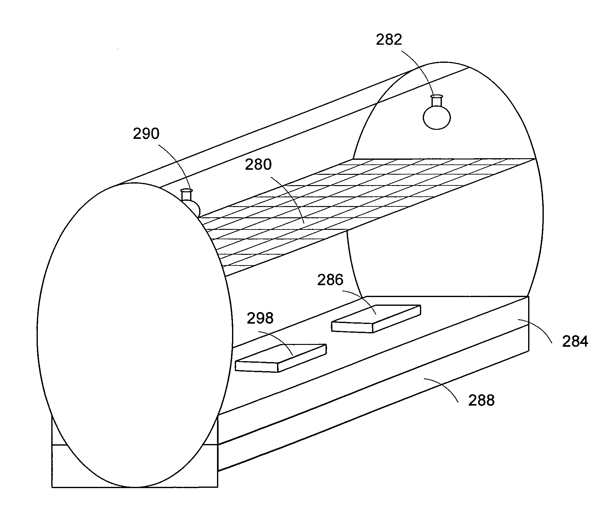
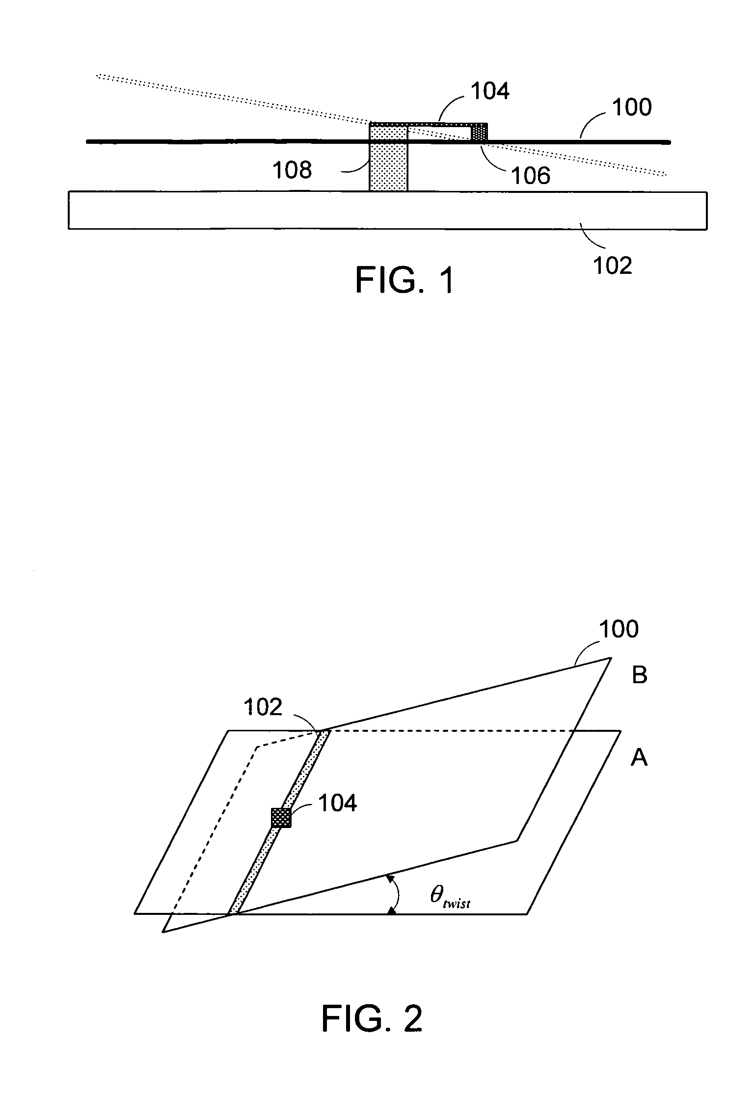
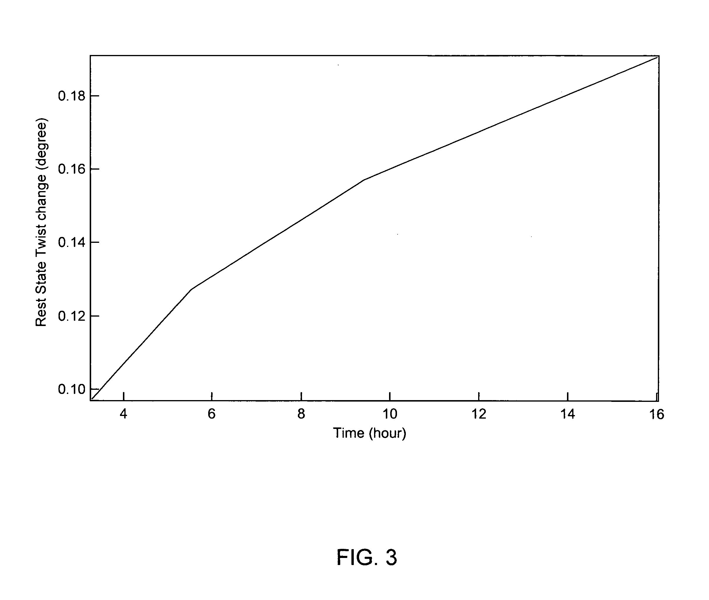
[0032]Disclosed herein is a method for improving the lifetime of MEMS devices with deformable elements by illuminating the devices with intense light before the devices are used in normal service. The invention is applicable to MEMS devices with deformable elements, especially the deformable elements that may accumulate residual plastic deformation over operation time. In view of many possible variations, the invention will be discussed in the following with reference to particular examples wherein the MEMS devices are micromirror devices each having a deformable hinge attached thereto a reflective and deflectable mirror plate. Depending upon different configurations, the deformable hinge can be a torsion hinge, flexure hinge, or other type of hinge. Even the micromirror devices in the following discussion may have a variety of different configurations. It will be understood by those skilled in the art that the following discussion is for demonstration purposes only, and should not ...


PUM


Abstract

A microelectromechanical device with a plastically deformable element of is exposed to illumination light so as to elongate the lifetime of the device on the customer side.

Description

TECHNICAL FIELD OF THE INVENTION[0001]The present invention is related generally to the art of microstructures, and, more particularly, to methods for improving the lifetime of microstructures with deformable elements.BACKGROUND OF THE INVENTION[0002]Microstructures such as microelectromechanical devices (hereafter MEMS devices) having deformable elements may suffer from device failure when the deformable elements deform plastically. Plastic deformation may be accumulated over operation time and result in residual plastic deformation at the natural resting state. The residual plastic deformation alters the operational states of the MEMS device—causing device failure. When such MEMS device is a member of an array of MEMS devices, the MEMS device may fail when one or more deformable elements of the MEMS devices in the array have residual plastic deformation more than a certain amount relative to the deformable elements of other MEMS devices in the array. Illumination of the deformable...

Claims


Application Information

Patent Timeline
Patent Type & Authority Patents(United States)
IPC IPC(8): G02B26/00
CPCG02B26/0833B81C1/00674
Inventor DOAN, JONATHAN
Owner TEXAS INSTR INC
Features
  • R&D
  • Intellectual Property
  • Life Sciences
  • Materials
  • Tech Scout
  • Unparalleled Data Quality
  • Higher Quality Content
  • 60% Fewer Hallucinations
Learn More