Retroreflective device comprising gradient index lenses

a technology of gradient index and retroreflective device, which is applied in the direction of optics, lenses, instruments, etc., can solve the problems of limited field of view of devices, high cost of components, and inability to cover arbitrary angles of incidence across a full hemisphere, and achieve the effect of wide field

Inactive Publication Date: 2007-01-30
BAE SYSTEMS PLC
View PDF11 Cites 4 Cited by
  • Summary
  • Abstract
  • Description
  • Claims
  • Application Information

AI Technical Summary

Benefits of technology

[0010]The present invention aims to address at least one of the above-identified disadvantages associated with the retroreflective devices currently in common use. Preferred embodiments of the invention aim to overcome, or at least re

Problems solved by technology

Consequently, such components are expensive to make, but they have the advantage of providing diffraction limited performance which gives excellent quality to the reflected beam.
Disadvantageously, however, such devices exhibit a limited field of view which varies with the construction details, but which cannot allow coverage of arbitrary angles of incidence across a full hemisphere without grouping several reflectors together, where each reflector is pointed in a different direction.
This increases the expense and the complexity of constructing such devices with high field of view.
The main disadvantage of this design is that the reflected radiation is subject to severe spherical aberration for non-paraxial rays, and this can strongly reduce the far-field intensity of the reflec

Method used


Image

  • Retroreflective device comprising gradient index lenses
  • Retroreflective device comprising gradient index lenses
  • Retroreflective device comprising gradient index lenses

Examples


first embodiment

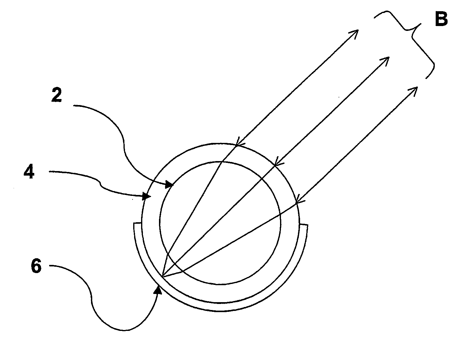
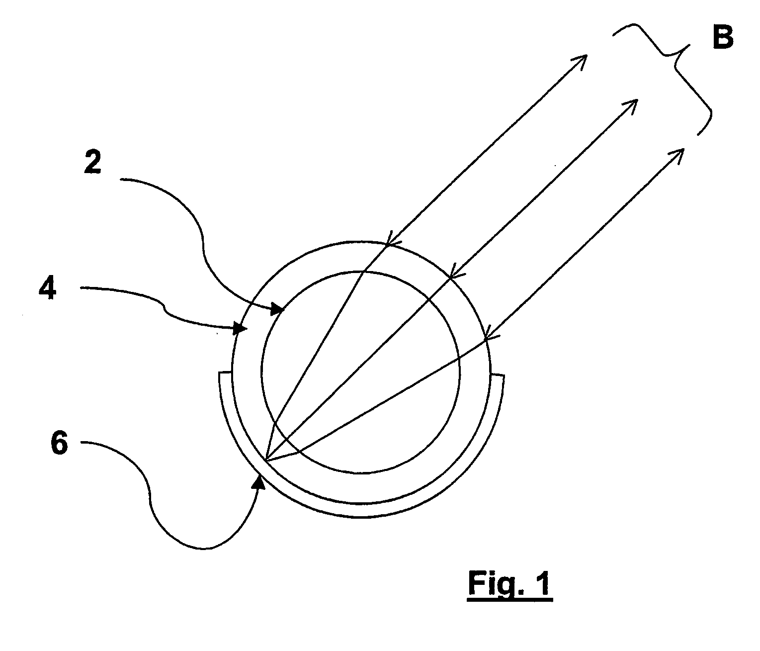
[0024]FIG. 1 shows a retroreflective device based on a GRIN-sphere lens arranged in accordance with the invention. The upper hemisphere of the mechanical surface of the GRIN-sphere lens 2, shown as a solid circle 2, is the surface through which an incident radiation beam B (which is assumed to be a parallel beam) passes into the GRIN-sphere lens.

[0025]In order to improve the optical characteristics of the device, the GRIN-sphere lens 2 is clad in, or otherwise coated with, a transparent material 4 having a uniform refractive index of a particular, desired value. The transparent material has a uniform thickness, and has an outer spherical surface which is arranged concentric with the outer surface of the GRIN-sphere lens 2. The upper surface of the transparent material forms the entrance face of the device. Although not shown in FIG. 1, the entrance face of the transparent material 4 (and indeed the equivalent surfaces shown in other figures hereof) may be provided with an anti-refle...

second embodiment

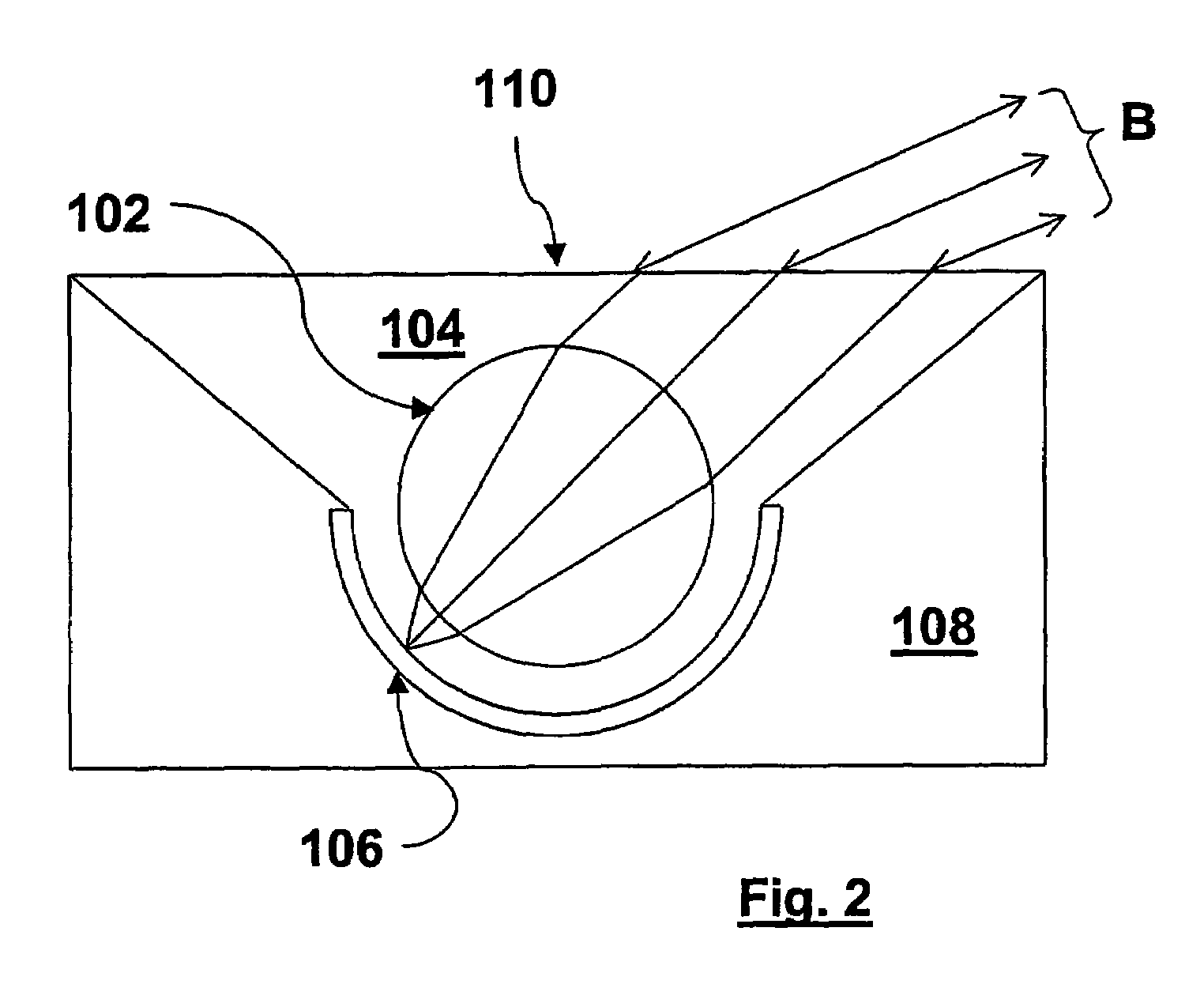
[0030]the invention is shown in FIG. 2. Here, components similar to that shown in FIG. 1 are given the same reference numerals, incremented by 100. The GRIN-sphere lens 102 is immersed in, and may be at least partially supported by, an environment comprising a transparent solid material 104 of uniform refractive index, having a chosen relationship with the refractive index at the GRIN-sphere surface. The transparent material may be supported by a solid structure 108, which may for example have a lower surface formed, for example as a planar surface, so as to stably support the device in a preferred orientation on a horizontal surface. A reflective material 106 is formed on a boundary between the transparent material 104 and the solid structure 108.

[0031]Alternatively, depending for example upon the use for which the device is intended and / or the treatment to which it may be subjected, the lens may be immersed in a transparent liquid material and supported by thin filaments (not show...

third embodiment

[0033]FIG. 3 shows the invention, which reduces angularly-dependent retroreflectivity and polarisation effects. Here, components similar to those previously described have the same reference numerals, incremented by 100. The transparent material 204 is given a hemispherical outer shape. The material may in this embodiment be protected by a transparent optical dome casing (not shown) made of a relatively hard material, such as glass. This arrangement reduces the variation of reflection performance with incidence angle, compared to the embodiment shown in FIG. 2. The rays encountering the GRIN-sphere can be made effectively paraxial with respect to the lens formed by the outer surface 210, provided that the radius of curvature of the outer surface is made sufficiently large compared to the radius of the outer surface of the GRIN-sphere lens 202. Due to the preferred relatively large radius of curvature of the outer surface of the transparent material 204 at the entrance face 210, the ...


PUM

PropertyMeasurementUnit
Radiusaaaaaaaaaa
Transparencyaaaaaaaaaa
Distributionaaaaaaaaaa

Abstract

A retroreflective device comprising a substantially spherical graded refractive index lens, referred to as a GRIN-sphere lens (2), a reflective part for retroreflecting (6) a radiation beam (B) passing through the graded refractive index lens and, at least partially surrounding the lens, a transparent material (4) having a substantially uniform refractive index.

Description

FIELD[0001]This invention relates to retroreflective devices; the term “retroreflective devices” as used herein being intended to encompass generally optical components used for returning radiation automatically from a remote location toward an optical source.BACKGROUND[0002]Retroreflective devices are designed to reflect radiation back towards its source, and such devices are thus frequently used to return radiation toward radiating optical sources when it is inconvenient or undesirable to actively generate radiation at locations, remote from the optical sources, which need to send response radiation to fixed or mobile base locations at which the radiating optical sources are sited. Common examples include the use of special reflective materials for safety clothing or signage, cat's eye markers in road surfaces, and measurement points in land surveying or robotic machinery. Retroreflective devices may also be used in combination with optical modulation mechanisms in order to establ...

Claims


Application Information

Patent Timeline
IPC IPC(8): G02B3/00G02B17/00G02B5/128
CPCG02B5/128C03C12/02
Inventor HANDEREK, VINCENT ANDREILAYCOCK, LESLIE CHARLES
Owner BAE SYSTEMS PLC
Why Eureka
Try Eureka