
System and method for planning energy supply and interface to an energy management system for use in planning energy supply

a technology of energy management system and energy supply, applied in the direction of electric devices, process and machine control, instruments, etc., can solve the problems of limiting the ability of optimally deploying individual energy suppliers in an overall plan, task cannot be performed satisfactorily in a centralized manner, and automated optimization cannot take place in this manner alon

Inactive Publication Date: 2007-01-30
SIEMENS AG
View PDF9 Cites 123 Cited by
  • Summary
  • Abstract
  • Description
  • Claims
  • Application Information

AI Technical Summary

Benefits of technology

"The present invention provides a system and method for planning energy supply for energy consumers by exchanging energy planning information between an energy coordinating body and energy suppliers or energy management systems. The system includes an interface for exchanging information and negotiating an energy supply specification. The invention allows for automated optimization and decentralized energy planning, especially in markets with multiple energy suppliers and multiple energy consumers. The system can be used by energy coordinating bodies and energy suppliers or management systems. The technical effects of the invention include improved efficiency and efficiency of energy supply planning, increased flexibility, and improved decision-making for energy consumers and suppliers."

Problems solved by technology

This limits the capability of optimally deploying individual energy suppliers in an overall plan.
Consequently, the individual power plants deliver the required output or, alternatively, report faults.
However, when one or more power plants provide energy for different energy service / output buyers at the same time or in series, this task can no longer be performed satisfactorily in a centralized manner.
Therefore, automated optimization cannot take place in this manner alone (i.e., without additional knowledge).
Accordingly, output reserves inherent in power plants cannot be utilized.
However, these protocols are posing technical and economic problems due to the growth of national and international power pools and regional centers, and increases in utility data communication applications.

Method used


Image

  • System and method for planning energy supply and interface to an energy management system for use in planning energy supply
  • System and method for planning energy supply and interface to an energy management system for use in planning energy supply
  • System and method for planning energy supply and interface to an energy management system for use in planning energy supply

Examples


Embodiment Construction

[0070]As employed herein, the term “energy supplier” shall expressly include, but not be limited to, one or more electric power plants, nuclear power plants, fossil power plants, hydroelectric power plants, solar power plants, wind farms, and / or geothermal power plants.

[0071]As employed herein, the term “person” shall expressly include, but not be limited to, a natural person, firm, corporation, association, group or organization.

[0072]As employed herein, the term “energy consumer” shall expressly include, but not be limited to, a person, a facility, and / or a business entity which consumes energy, either directly or indirectly, from an energy supplier.

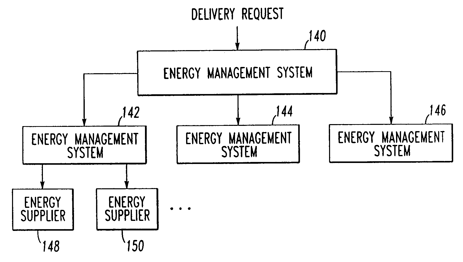
[0073]As employed herein, the term “energy management system” shall expressly include, but not be limited to one or more persons, facilities, and / or business entities which coordinate, broker, sell and / or distribute energy from one or more energy suppliers to one or more energy consumers and / or other energy management systems.

[0074]As ...


PUM


Abstract

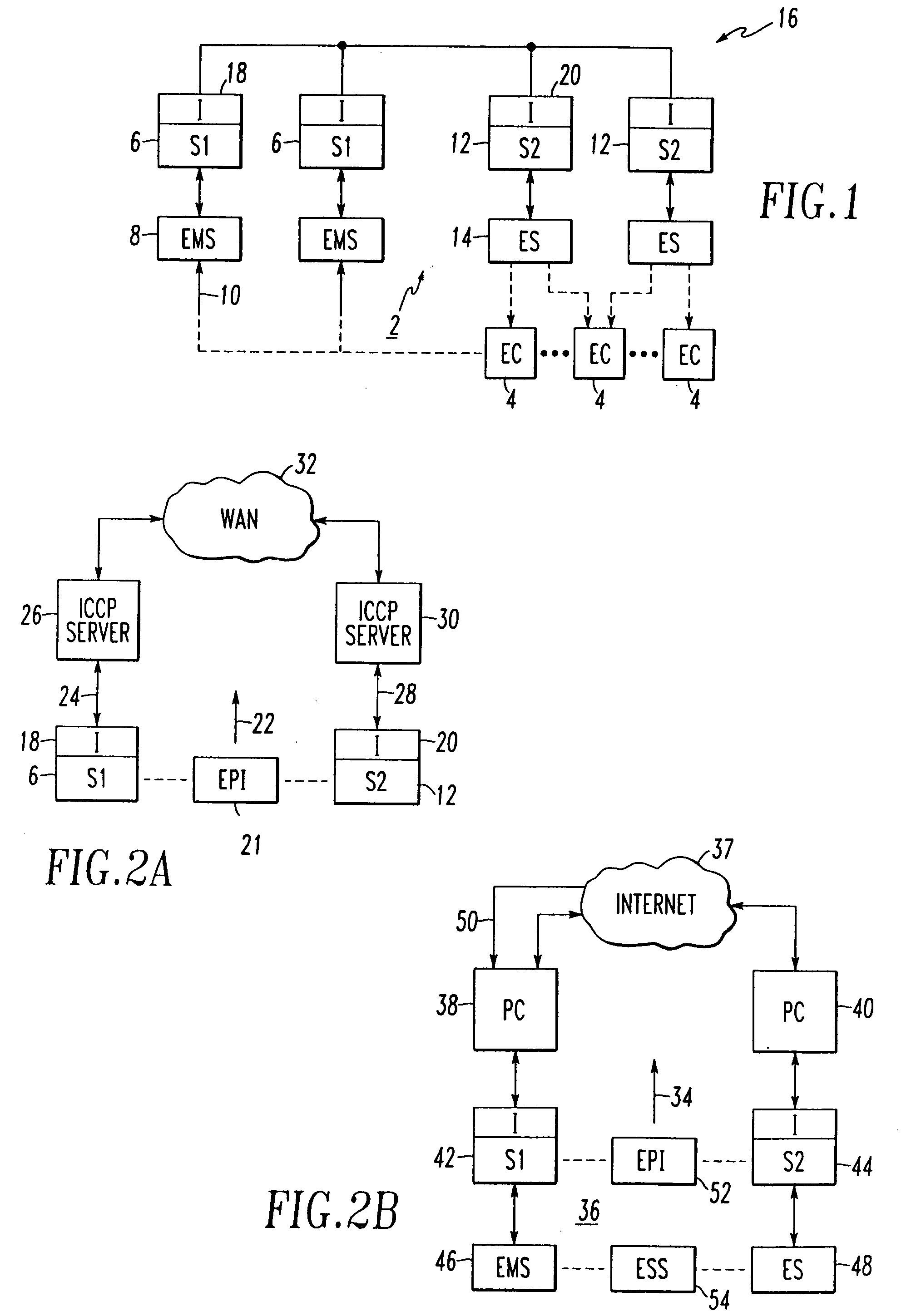
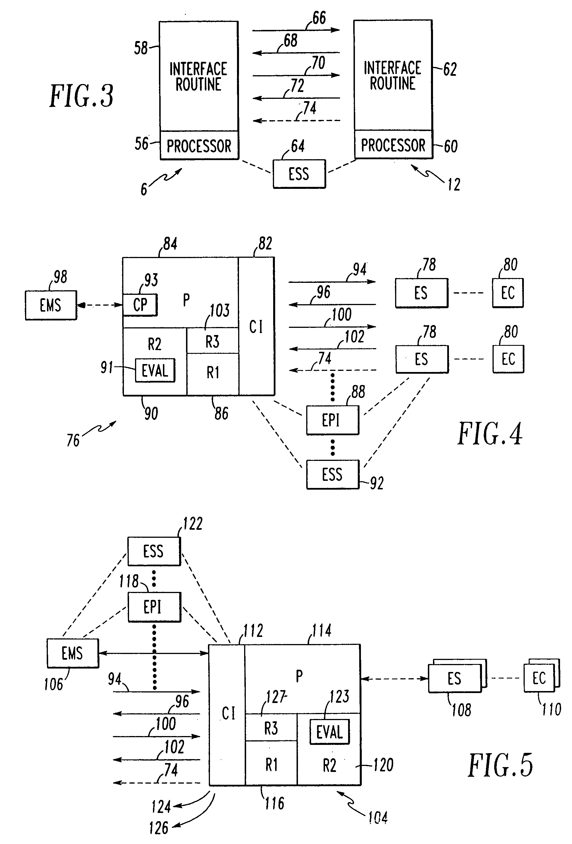
A system for planning energy supply for energy consumers includes a first sub-system operatively associated with an energy coordinating body, such as an energy management system, and second sub-systems operatively associated with corresponding energy suppliers, such as power plants. A global communication network, such as the Internet, is employed between the first and second sub-systems. Each of the sub-systems includes an interface for exchanging energy planning information between the sub-systems and for negotiating an energy supply specification from the energy supplier to the energy consumers.

Description

[0001]This application claims the benefit, under 35 U.S.C. § 120, of patent application Ser. No. 09 / 671,916, filed Sep. 28, 2000, the contents of which are incorporated by reference herein in their entirety.BACKGROUND OF THE INVENTION[0002]1. Field of the Invention[0003]The invention relates to a system for planning energy supply and, more particularly, to such a system for negotiating an energy supply specification with one or more energy suppliers for energy consumers. The invention also relates to a method for planning energy supply. The invention further relates to an interface to an energy management system for use in planning energy supply.[0004]2. Background Information[0005]If several energy suppliers join forces, then more profitable service might be provided through a skillful combination of the performance of the individual energy suppliers. This would, however, require the utilization of knowledge of parameters that influence the cost / benefit relationship for the individ...

Claims


Application Information

Patent Timeline
Patent Type & Authority Patents(United States)
IPC IPC(8): G05D9/00H02J3/00
CPCG06Q40/04G06Q50/06H02J3/008Y04S10/58Y04S50/10Y04S10/50
Inventor WEISS, ANTON
Owner SIEMENS AG
Learn More