
Integrated control apparatus for vehicle

a technology of integrated control apparatus and control apparatus, which is applied in the direction of external condition input parameters, non-deflectable wheel steering, brake components, etc., can solve the problems of inability to accurately estimate the current friction coefficient of the road surface, the integrated control apparatus disclosed in the publications does not reflect the state, and the expected vehicle stability is not attained. , to achieve the effect of enhancing vehicle stability

Inactive Publication Date: 2007-01-30
JTEKT CORP
View PDF4 Cites 29 Cited by
  • Summary
  • Abstract
  • Description
  • Claims
  • Application Information

AI Technical Summary

Benefits of technology

The present invention provides an integrated control apparatus for a vehicle that integrates the control of actuators in at least two of the steering system, brake system, and drive system in an optimally distributed condition according to the behavioral condition of the vehicle and the state of the road surface without using the friction coefficient of the road surface. This results in improved vehicle stability and reduced disturbance. The apparatus includes a vehicle behavioral-quantity detection device, target vehicle behavioral-quantity calculation device, vehicle-control target value calculation device, estimation device for grip factor, distribution-ratio-setting device, and control device for the actuators. The apparatus can also include an acquisition device for acquiring peripheral condition of the vehicle and a calculation device for calculating the radius of an approaching curve of a lane in which the vehicle is running.

Problems solved by technology

However, the integrated control apparatus disclosed in the publications do not reflect the state of a road surface on control.
As a result, in some cases, expected vehicle stability is not attained.
However, accurately estimating the current friction coefficient μ of the road surface is difficult.
Also, estimating a momentary change in the friction coefficient of the road surface is difficult.
Therefore, accurately estimating the grip limit force Fg, which varies according to the state of the road surface, is difficult.
However, using the tire margin for control before the critical region of the vehicle is reached is inadequate.

Method used


Image

  • Integrated control apparatus for vehicle
  • Integrated control apparatus for vehicle
  • Integrated control apparatus for vehicle

Examples


Embodiment Construction

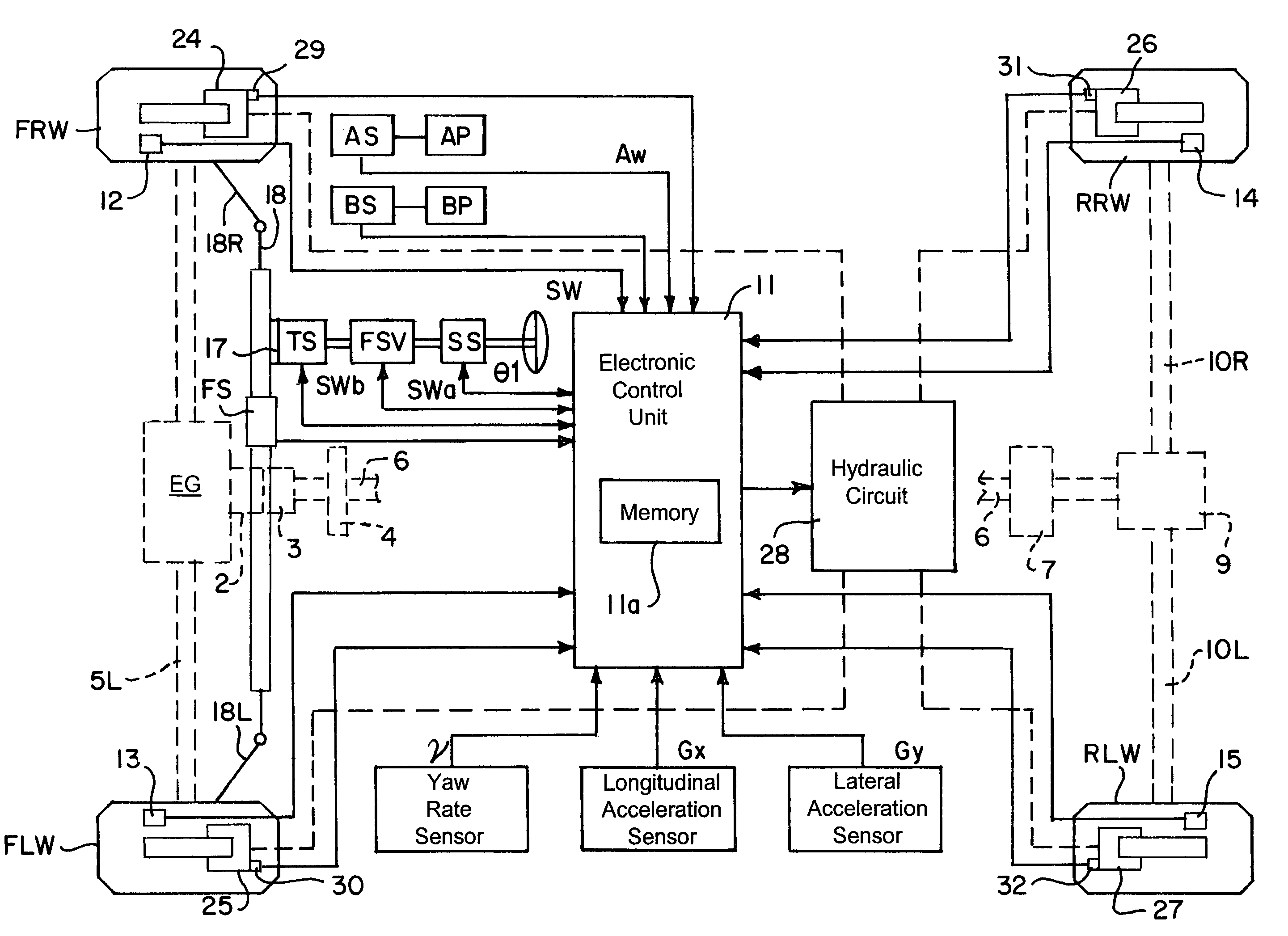
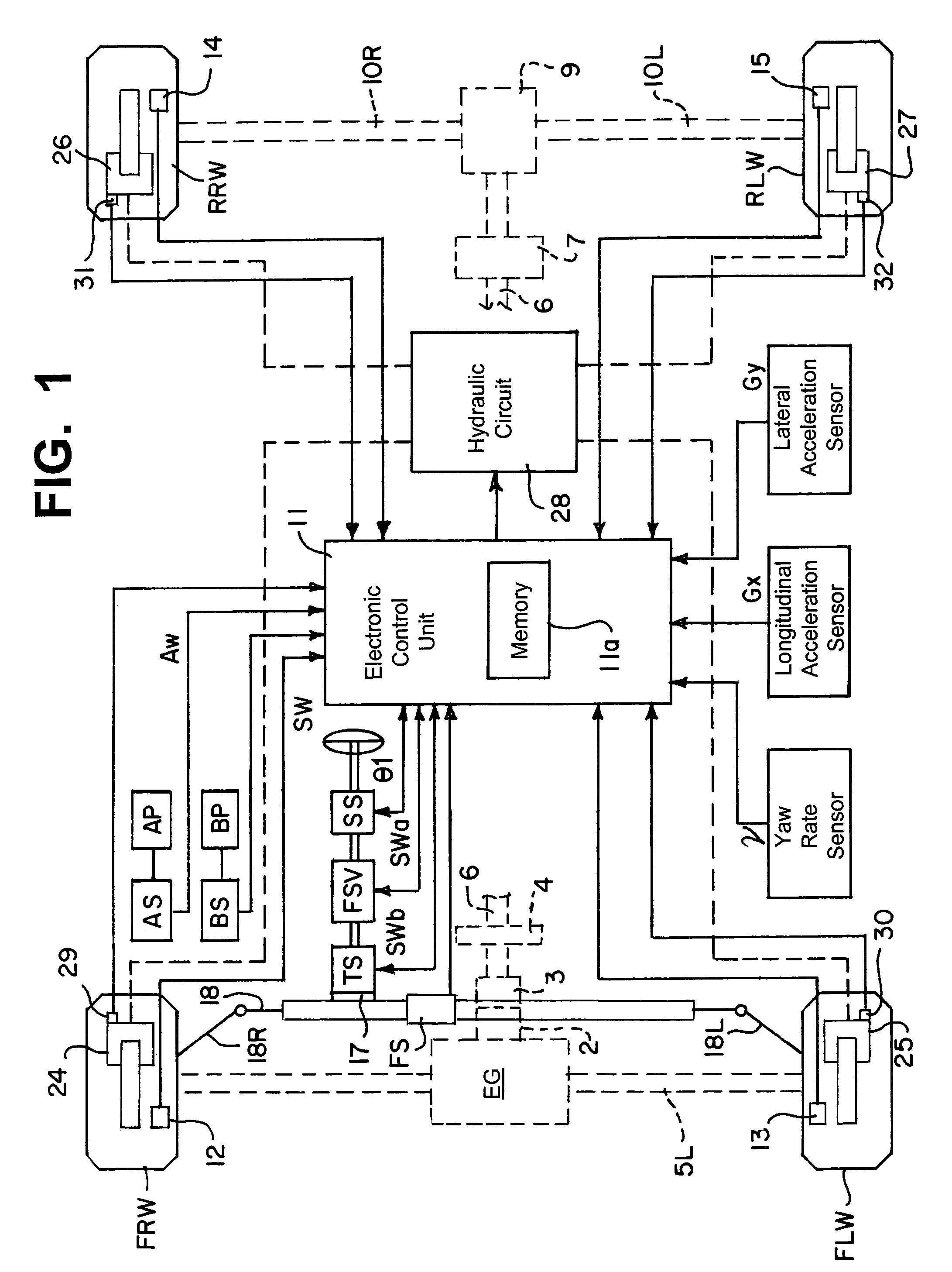
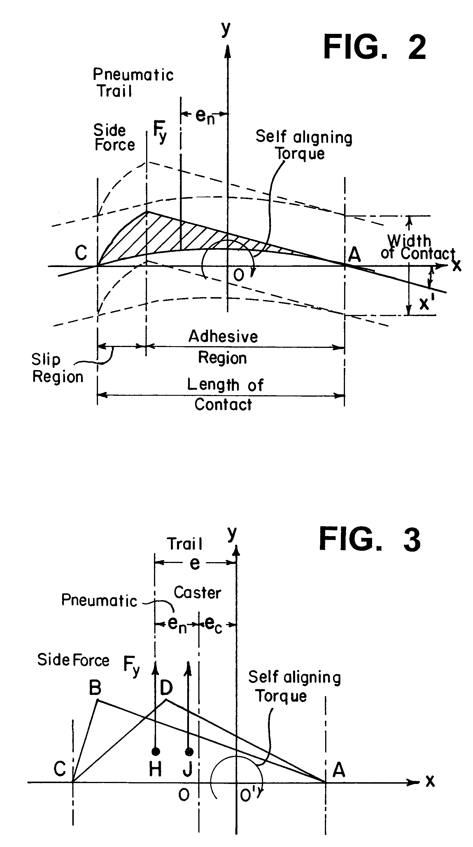
[0051]An embodiment of the present invention will next be described with reference to FIGS. 1 to 9. FIG. 1 is a schematic, configurational block diagram of an integrated control apparatus for a vehicle according to the present embodiment. FIG. 2 is a graph showing the relation between self-aligning torque and side force in an ordinary vehicle whose tires are rolling while skidding. FIG. 3 is a simplified view of the situation depicted in FIG. 2, showing the relation between self-aligning torque and side force. FIG. 4 is a block diagram of an electronic control unit 11. FIG. 5 is a block diagram of a grip factor calculation section 41. FIG. 6 is an explanatory view showing a 2-wheel vehicle model having a front wheel and a rear wheel. FIG. 7 is a control flowchart. FIG. 8 is a graph showing a characteristic of side force vs. self-aligning torque. FIG. 9 is a graph showing a characteristic of self-aligning torque vs. steering-mechanism friction component, in relation to correction of ...


PUM


Abstract

An electronic control unit calculates a target yaw rate in accordance with a vehicle speed and a steering angle and calculates the yaw rate difference on the basis of the target yaw rate and an actual yaw rate. The electronic control unit estimates the grip factor of a front wheel to road surface and sets a distribution ratio for distribution of a vehicle-control target value among actuators of a steering system, a brake system, and a drive system in accordance with the estimated grip factor. The electronic control unit controls the actuators of the three systems in accordance with control instruction values distributed on the basis of the vehicle-control target value and the distribution ratio.

Description

INCORPORATION BY REFERENCE[0001]The present application claims priority under 35 U.S.C. §119 to Japanese Patent Application No. 2003-344743 filed on Oct. 2, 2003. The content of the application is incorporated herein by reference in its entirety.BACKGROUND OF THE INVENTION[0002]1. Field of the Invention[0003]The present invention relates to an integrated control apparatus for a vehicle capable of enhancing vehicular running stability.[0004]2. Description of the Related Art[0005]A conventionally known integrated control apparatus for a vehicle is disclosed in Japanese Patent Application Laid-Open (kokai) No. 9-109866. The integrated control apparatus for a vehicle combines braking force control with 4WS (4-wheel steering) steering-angle control and performs target follow-up control by use of yaw rate feedback, thereby enhancing vehicle stability during, for example, cornering. Japanese Patent Application Laid-Open (kokai) No. 2002-254964 also discloses another known integrated contro...

Claims


Application Information

Patent Timeline
Patent Type & Authority Patents(United States)
IPC IPC(8): G06G7/00B60K28/16B60T8/175B60R21/00B60K17/35B60R1/00B60R16/02B60T8/172B60T8/1755B60W10/20B60W30/00B60W30/02B60W40/068B60W40/10B62D6/00B62D37/00B62D101/00B62D103/00B62D111/00B62D113/00B62D119/00
CPCB60T8/172B60T8/17558B62D6/006B60W10/18B60W10/20B60W40/064B60K2741/283B60T2210/12B60W2550/148B60T2260/02B60W2552/40B60W2540/18
Inventor KATO, HIROAKIMOMIYAMA, MINEKAZUOHTA, TAKAYUKIKODAMA, AKIRA
Owner JTEKT CORP
Learn More