Delay locked loop for and FPGA architecture

a delay lock and fpga technology, applied in the direction of generating/distributing signals, instruments, computing, etc., can solve the problems of clock signal unacceptably degrade, limited fanout of a single source, and other problems such as clock degradation, to achieve the effect of reducing the number of clock trees

Inactive Publication Date: 2007-01-30
ACTEL CORP
View PDF13 Cites 8 Cited by
  • Summary
  • Abstract
  • Description
  • Claims
  • Application Information

AI Technical Summary

Benefits of technology

[0011]It is another object of the present invention to provide a flexible interface bet

Problems solved by technology

When the fanout becomes too large the clock signal will become unacceptably degraded.
Accordingly, the fanout that a single source is permitted to drive is limited.
However, problems other than clock degradation also occur with the use of clock trees.
When the devices being clocked from the clock buffers are located at varying distances from the clock buffer, the clock signal may become skewed due to the

Method used


Image

  • Delay locked loop for and FPGA architecture
  • Delay locked loop for and FPGA architecture
  • Delay locked loop for and FPGA architecture

Examples


Embodiment Construction

[0022]Those of ordinary skill in the art will realize that the following description of the present invention is illustrative only and not in any way limiting. Other embodiments of the invention will readily suggest themselves to such skilled persons.

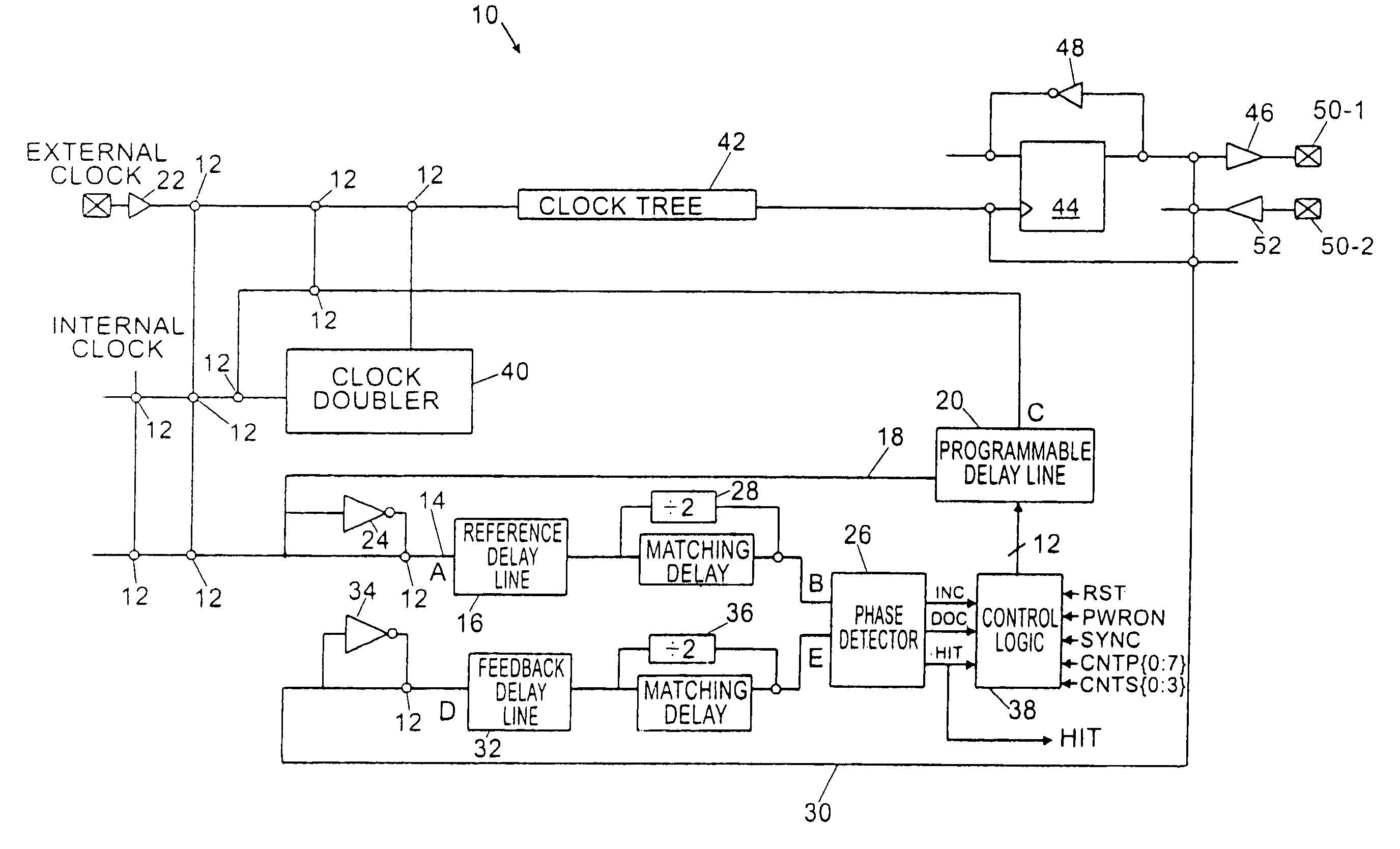
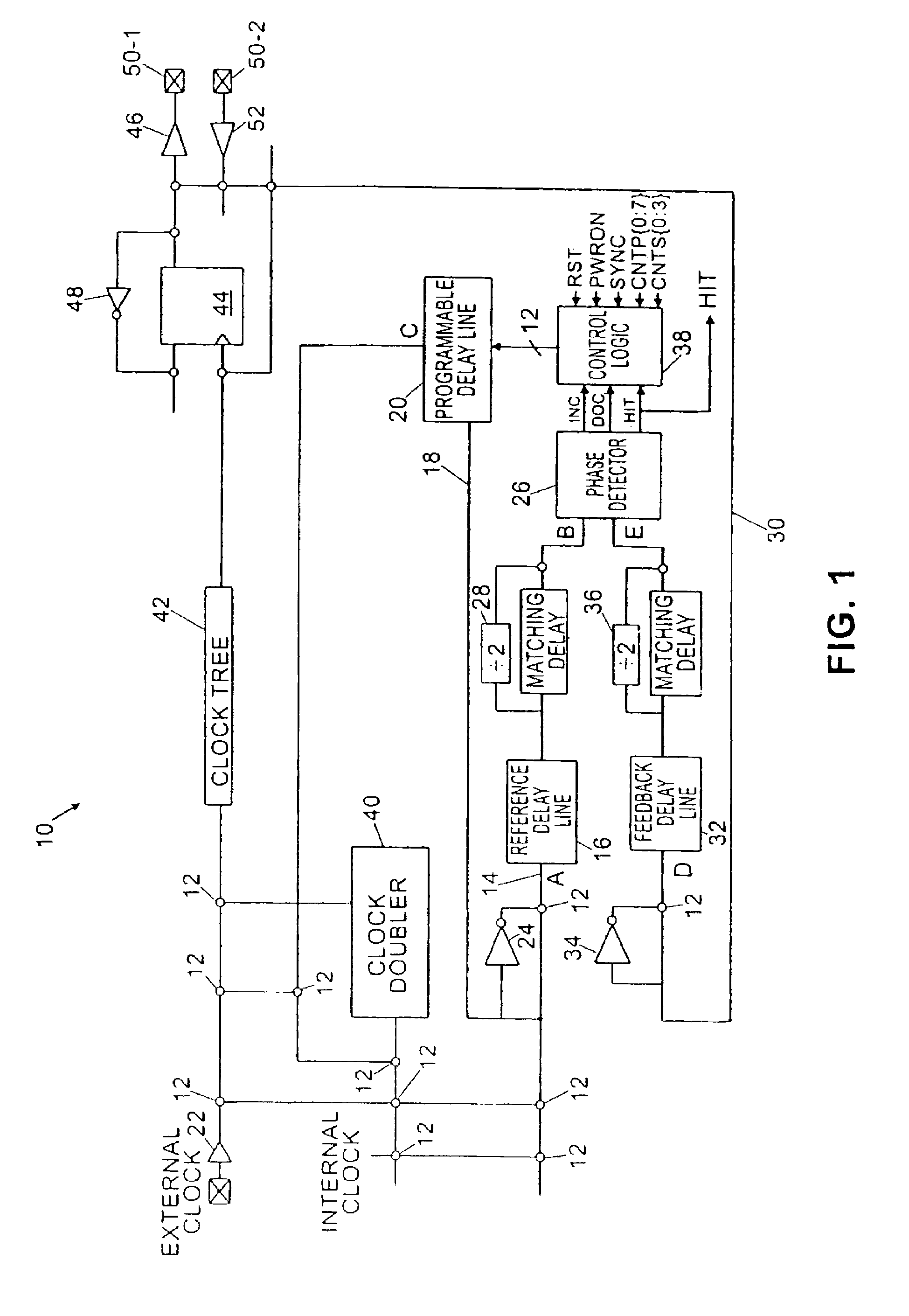
[0023]In FIG. 1, a diagram of a DLL 10 and some additional circuit elements according to the present invention are illustrated. Various portions of the diagram in FIG. 1 may be connected by programmable interconnect elements 12 that are illustrated as open circles. It will be appreciated by those of ordinary skill in the art that programmable interconnect elements 12 suitable for use according to the present invention may be any of several one time programmable or reprogrammable elements, including antifuses, EEPROM bits, SRAM bits or transistors.

[0024]In FIG. 1, a reference clock signal is supplied by either an INTERNAL CLOCK signal or EXTERNAL CLOCK signal that is programmably coupled by a programmable interconnect element 12 to the i...


PUM


Abstract

A DLL provides a deskew mode for aligning a reference clock that passes through a clock distribution tree to a feedback by adding additional delay to the feedback clock to align the feedback clock with reference clock at one cycle later. A 0 ns clock-to-out mode is provided by adding additional delay to account for an input buffer into a feedback path. The feedback clock can be doubled by a clock doubler with 50% duty cycle adjustment disposed in the feedback path. Flexible timing is aligning the reference clock to the feedback clock is obtained with additional delay elements disposed in the feedback and reference clock paths.

Description

CROSS-REFERENCE TO RELATED APPLICATIONS[0001]This application is a continuation of co-pending U.S. patent application Ser. No. 10 / 722,636, filed Nov. 25, 2003 now U.S. Pat. No. 6,976,185, which is a continuation of U.S. patent application Ser. No. 09 / 519,311, filed Mar. 6, 2000, now U.S. Pat. No. 6,718,477, which are hereby incorporated by reference as if set forth herein.BACKGROUND OF THE INVENTION[0002]1. Field of the Invention[0003]The present invention relates to a delay locked loop (DLL). More particularly, the present invention relates to a DLL in a field programmable gate array (FPGA).[0004]2. Background Art[0005]With the advent of FPGA architectures having greater complexity, it is well understood by those of ordinary skill in the art that extensive digital systems can be implemented in FPGA devices. These FPGA devices may include many dockable elements such as D-Type flip flops and blocks of user assignable static random access memory (SRAM). The D-type flip flops and the u...

Claims


Application Information

Patent Timeline
IPC IPC(8): G06F1/08
CPCG06F1/08
Inventor PLANTS, WILLIAM C.MAZUMDER, NIKHILKUNDU, ARUNANGSHUJOSEPH, JAMESWONG, WAYNE W.
Owner ACTEL CORP
Why Eureka
Try Eureka