
Collapsible crowd control barrier

a crowd control and barrier technology, applied in the field of crowd control barriers, can solve the problems of masses of people easily rocking the fences, difficult to set up and remove, and ineffective ability to stop someone, etc., and achieve the effect of convenient and rapid deployment and connection

Inactive Publication Date: 2007-02-06
ALL ACCESS STAGING & PRODN
View PDF9 Cites 37 Cited by
  • Summary
  • Abstract
  • Description
  • Claims
  • Application Information

AI Technical Summary

Benefits of technology

[0015]Briefly and in general terms, the present invention is directed to a modular barrier that is used to control crowds at various scenes and events by providing a tubular top rail with a rearward projecting boss that defines a tubular wall which includes a horizontal bore, a journal bore and an axel and is formed with longitudinal spaces for struts. Crowd control barriers require a durable resistance to the forces generated by a surging crowd but yet constructed to be easily and rapidly deployed and connected together. Many largely populated events require security to be present behind the barriers for extended periods of times. For this embodiment, a step is provided to allow security to stand on the barrier elevated to see above a crowd. The formation of the top rail and tubular wall create an efficient surface for gripping in both the sense that one may easily hold the barrier there when connecting it to an adjacent one and in the sense that it provides a comfortable and sturdy support to grip for security when standing on the barrier step.
[0016]Various secure barricade configurations may be formed with the barrier. In one embodiment, the barrier module includes a hinged gate hung from the barrier frame. The hinged gate opens and can be set at an angle to the frame to connect on its free side to an adjacent barrier module when an angular barricade line is undesirable. The gate includes a latch block that abuts a block catch on the frame along abutting surfaces which angle at an oblique angle to the path of rotation of the gate to, upon abutting form a relatively low profile thickness so as to minimize any obstruction when folded down on the base.
[0017]The hinged gate also provides a pathway by which security personnel may cross from the safe area side of the barrier into the crowd area side freely without incurring the risk of scaling over the barrier and injure themselves or others and conveniently return to the safe area side without having to go all the way around to the ends of the barrier.

Problems solved by technology

While wooden barricades have been useful for signaling where one should not enter and are easy to setup, their ability to stop someone has largely been ineffective.
Likewise, barriers such as fencing are effective at stopping a few people but are difficult to set up and remove, and have proven largely ineffective at events with large crowds were tragically, masses of people easily rock the fences until they crash and people are crushed by the crowd.
While many metal barriers of sturdy construction have been previously developed, such barriers were relatively heavy demanding considerable labor to set up and move about.
Barriers with lightweight metal such as aluminum were then developed, and while lighter, lacked endurance or were cumbersome to manipulate.
The problem with the construction of barrier modules at present is that to meet durability requirements most are made of heavy material such as steel making them inefficient for handling and connecting together to form a barrier line.
Steel constructed barriers, while sturdy, are often constructed with rectangular tubing and are overall difficult to grasp.
Gripping a heavy rectangular surface while trying to connect two barriers together requires considerable effort and often results in the workman losing the frame causing it to fall and take damage.
Another problem with barrier connectors is the sturdiness of the connector itself.
While simple latches and pins may be sufficient to link barrier modules together, such a solution fails to provide durability against forces generated by a large crowd.
The latches and cotter pins tend to break or bend when resisting the crowd forces.
Such devices suffer the shortcoming that the connector of the pivotal struts to the top o the barrier frame are incapable of withstanding high crowd forces and are themselves inexpensive to make.
Connectors between the barrier modules often lock load carrying capability and many require time to assemble.
Such connectors are unsuitable for concert venues where set up and breakdown time is very limited.
Another problem with barriers of the present is their lack of user friendliness.
Security is often located behind the barriers in case someone is able to get past one but that limits the security from being able to access the crowd if needed.
The problem with the De Boer solution is that while security personnel may be elevated above the crowd, such a barrier design does not take into account the fact that personnel must stand on the step without upper body support, often for an extended period of time.
While De Boer shows a rounded rail top wall on which a workman may arguably rest his or her hand, it is challenging to maintain a grip on such a singular surface for extended periods of time.
The De Boer design also lacks a feature which enables security personnel to exit from behind the barrier and return effectively.
While personnel may be able to spot problems in the crowd, getting access to those problems from behind a barrier is another issue, as is returning to the secure side of the barrier.
While security personnel may scale the barrier from the security side to enter the crowd, such a maneuver risks further injury to the security personnel and to members of the crowd.
Another problem with barriers of today is the inflexibility of configuring them to the shape of the perimeter of the area to be protected.
Today's barriers are cumbersome and lack adaptability to the non-linear perimeters of many venues.
For instance, when an area requires a barricade to form a semi-circular formation or right angles at any point, the previously proposed barriers fail to provide an effective and efficient means of linking adjacent barriers to achieve this purpose.
Such barriers are not suitable for the regulation of large crowds of people because they're construction is either too lightweight or ineffective at keeping people out of a restricted area.
Such a sheet is easily compromised and people will be able to pass through the barrier at will.

Method used


Image

  • Collapsible crowd control barrier
  • Collapsible crowd control barrier
  • Collapsible crowd control barrier

Examples


Embodiment Construction

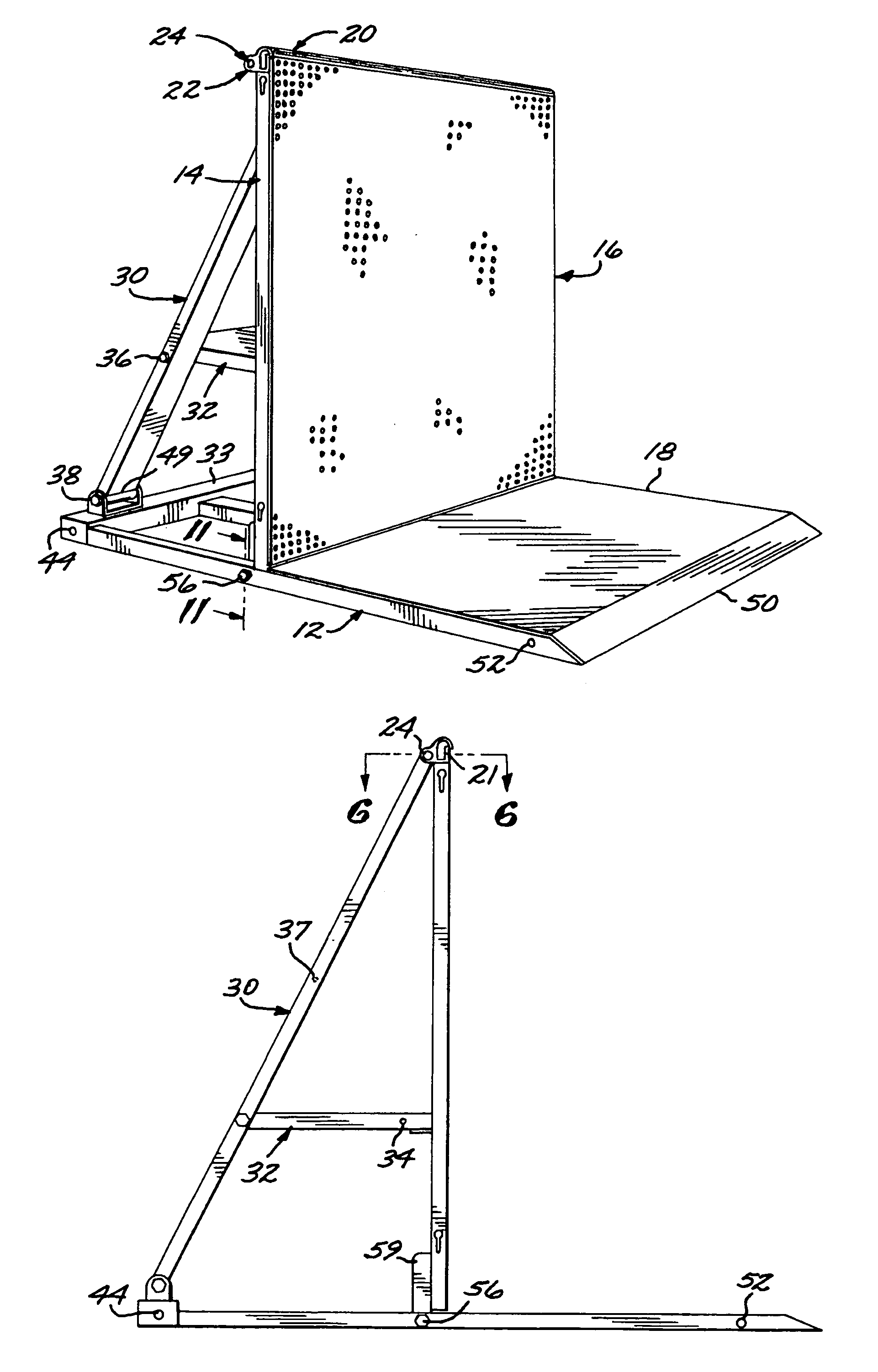
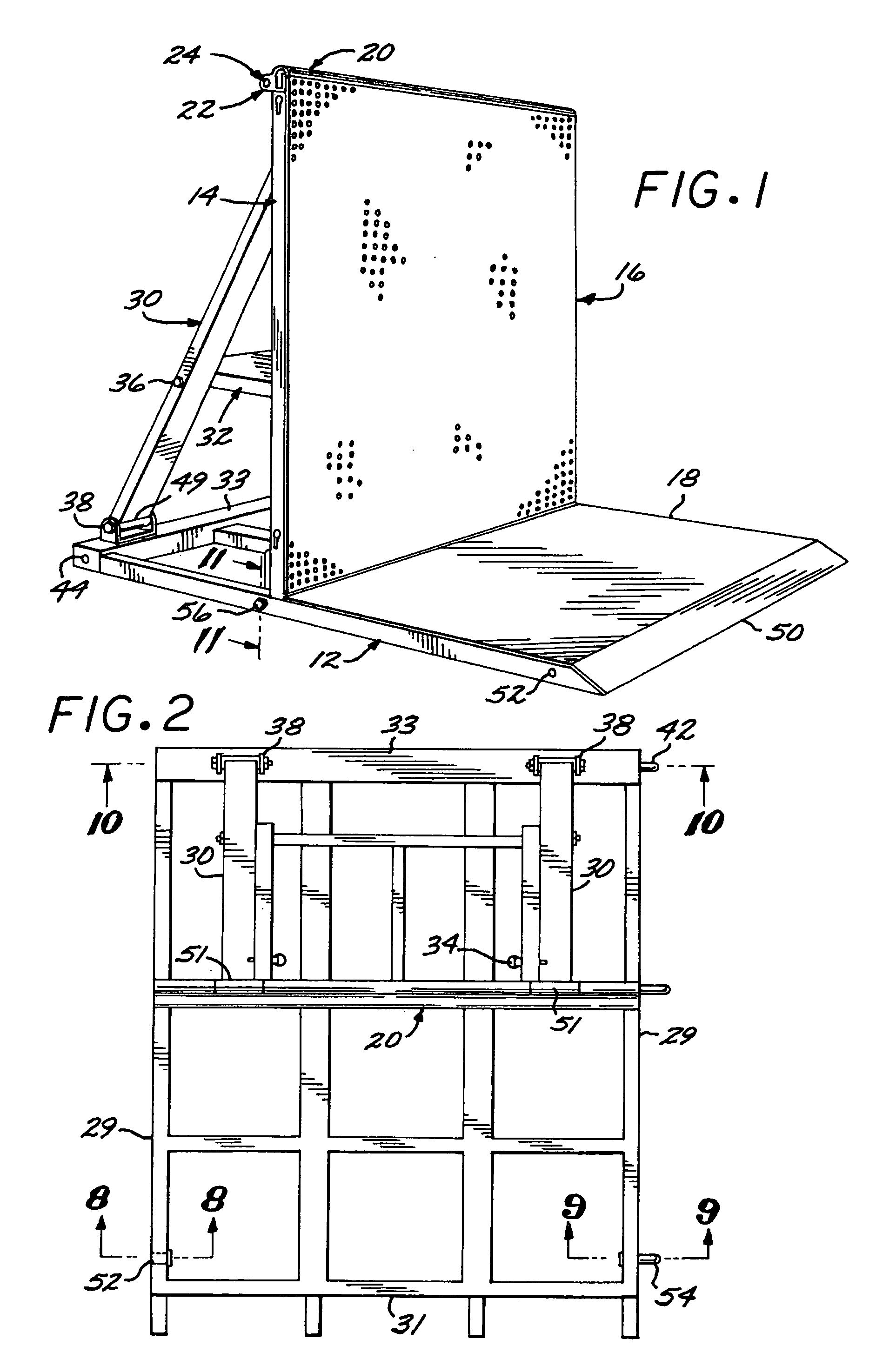
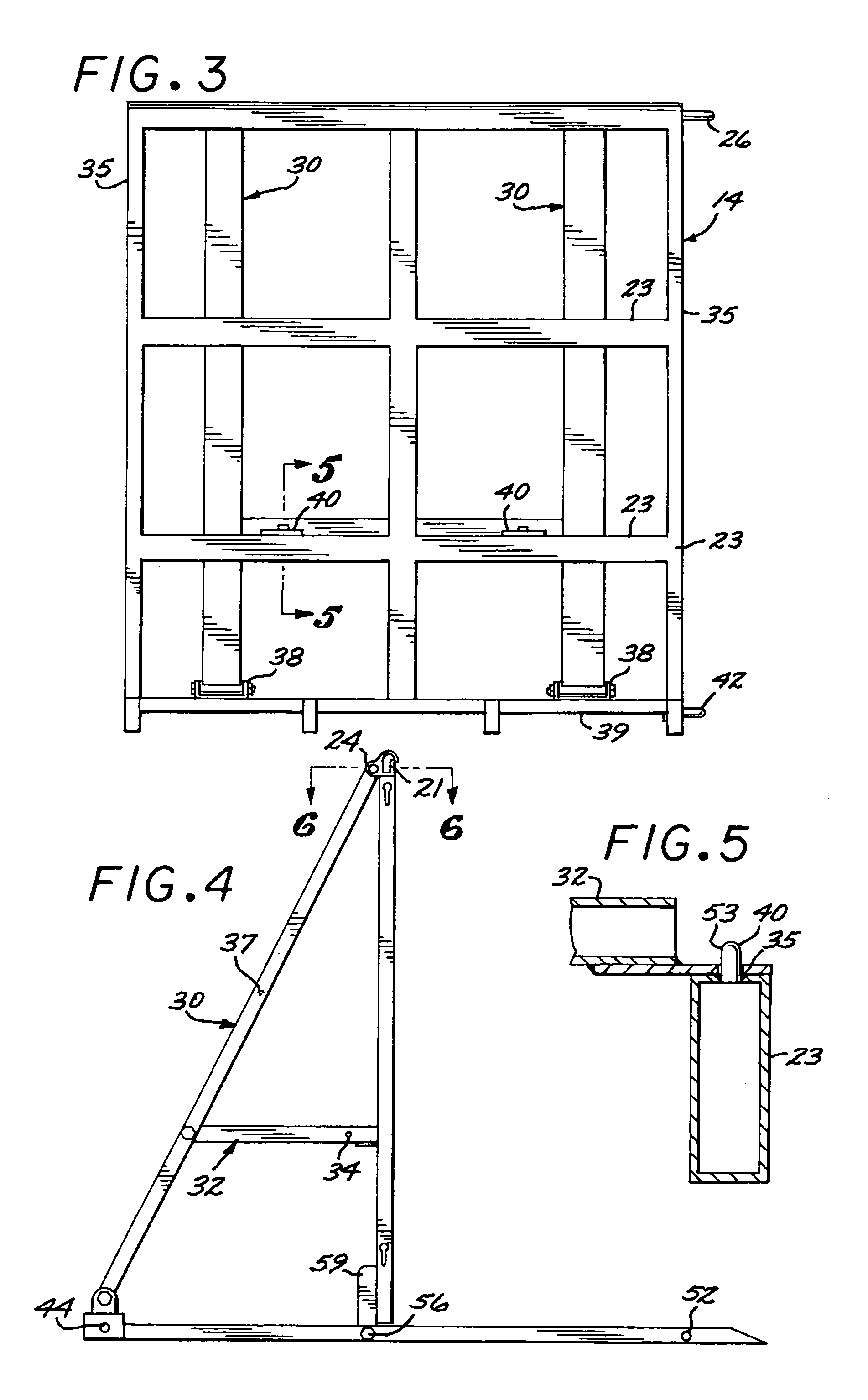
[0041]Referring to FIGS. 1, 6 and 7, the modular crowd control barrier 10 of the present invention includes generally, a base frame 12 surmounted by a barrier frame 14 pivotable from an erect to a collapsible position shown in FIG. 12. The barrier frame is braced on its erect position by pivotally mounted struts 30. The barrier frame is of tubular construction and includes a hollow horizontal load bearing, rounded top rail 20 and a structurally integrated rearward projecting boss formed by a tubular wall 22. The tubular wall 22 defines a horizontal journal bore 24 and is formed along its length with longitudinally spaced, longitudinal clearance slots 28 receiving the upper extremities of the struts 30 (FIG. 1). An elongated axel 26 is received in the horizontal bore 24 to partially connect the upper ends of such struts in place (FIG. 1).

[0042]Referring to FIGS. 1 and 2, the horizontal base 12 is constructed of rectangular aluminum tube members to form a pair of longitudinal side tub...


PUM


Abstract

A modular crowd control barrier that is collapsible includes a rounded top rail and a rearward projecting horizontal boss with a bore and axel. The axel of one barrier connects to the respective bore of an adjacent barrier. A hinged gate with a latch and catch may pivotally connect adjacent barriers to each other.

Description

FIELD OF THE INVENTION[0001]The present invention relates to a crowd control barrier that is easily configured for connecting to adjacent barriers and for storage and handling.BACKGROUND OF THE INVENTION[0002]The field of crowd barriers has evolved according to the needs of the situation. From simple wooden barricades to chain link fencing, crowd barriers have been developed to regulate and partition people from specified areas. While wooden barricades have been useful for signaling where one should not enter and are easy to setup, their ability to stop someone has largely been ineffective. Likewise, barriers such as fencing are effective at stopping a few people but are difficult to set up and remove, and have proven largely ineffective at events with large crowds were tragically, masses of people easily rock the fences until they crash and people are crushed by the crowd. Crowd control barriers require a sturdy construction while also needing simple setup and breakdown characteris...

Claims


Application Information

Patent Timeline
IPC IPC(8): E04H17/14
CPCE01F13/022
Inventor EASTLAND, ERIK
Owner ALL ACCESS STAGING & PRODN
Learn More