Lightweight quick connector system

Inactive Publication Date: 2016-10-06
AP COUPLINGS INC
View PDF5 Cites 0 Cited by
  • Summary
  • Abstract
  • Description
  • Claims
  • Application Information

AI Technical Summary

Benefits of technology

The present invention provides a lightweight quick connector system for joining the ends of grooved pipe. The system has a simple design, is easy to handle, and can be quickly joined and disconnected. It provides a positive o-ring seal, a positive clip locking mechanism, and joiner and disconnectivity in a matter of seconds. The system can be used with flexible piping and has the ability to adapt to different types of connectors. It includes a groove engagement locking clip that securely locks the grooved pipe into the quick connector. The system is reliable, durable, and can be easily assembled and maintained. It also allows for easy disassembly and replacement of the pipe, connectors, or both. Overall, the lightweight quick connector system provides a faster and more efficient solution for joining grooved pipe ends.

Problems solved by technology

The amount of labor and cost of material for using this prior seal and coupling system are significant.
The time and effort in constructing the “prior seal and coupling system” is significant.
The “prior seal and coupling system” is of necessity a significant addition of weight and cost.
Reliability is another issue with the “prior seal and coupling system”.
In many cases the problem may have been uneven tightening.
Another problem with the “prior seal and coupling system” is the provision of so many sealing structures and forces that must be coordinated to give a good and positive seal.
Mismatch of these two simultaneous forces are often possible if the coupler is not assembled mindfully.
The care with which the coupler must be assembled and engaged can contribute to leakage failure, even if it is temporary and repairable with further expenditure of time and labor.

Method used


Image

  • Lightweight quick connector system
  • Lightweight quick connector system
  • Lightweight quick connector system

Examples


first embodiment

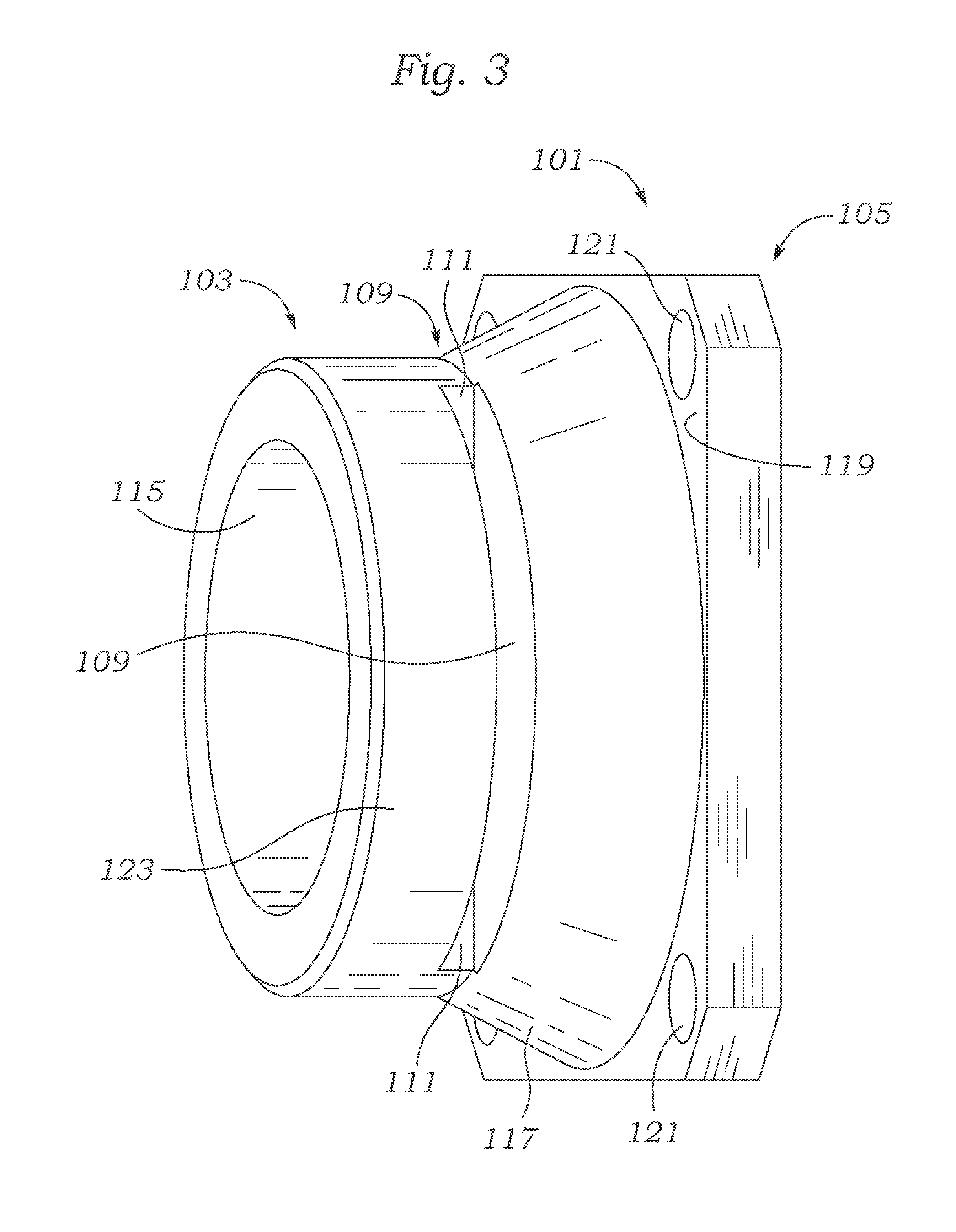
[0032]Referring to FIG. 3, a side view of a lightweight quick connector 101 is shown with one side having a grooved pipe receiving structure 103 and an opposite side having a flange 105 for bolted attachment to another structure. The quick connector 101 grooved pipe receiving structure 103 is seen to have a slot 109 that may be formed with a tangential cut through the material making up the grooved pipe receiving structure 103 and which may form exposed surfaces 111 of the material making up the grooved pipe receiving structure 103. Material behind exposed surfaces 111, which is not removed in the forming of the slots 109, regardless of how slots 109 are formed, represents the material which will determine the axial holding strength of the slots 109.

[0033]The slot 109 extends deeply enough into the material of grooved pipe receiving structure 103 that it cuts through and removes portions of the internal surface 115 of the quick connector 101. An opposite slot 109, not directly seen ...

second embodiment

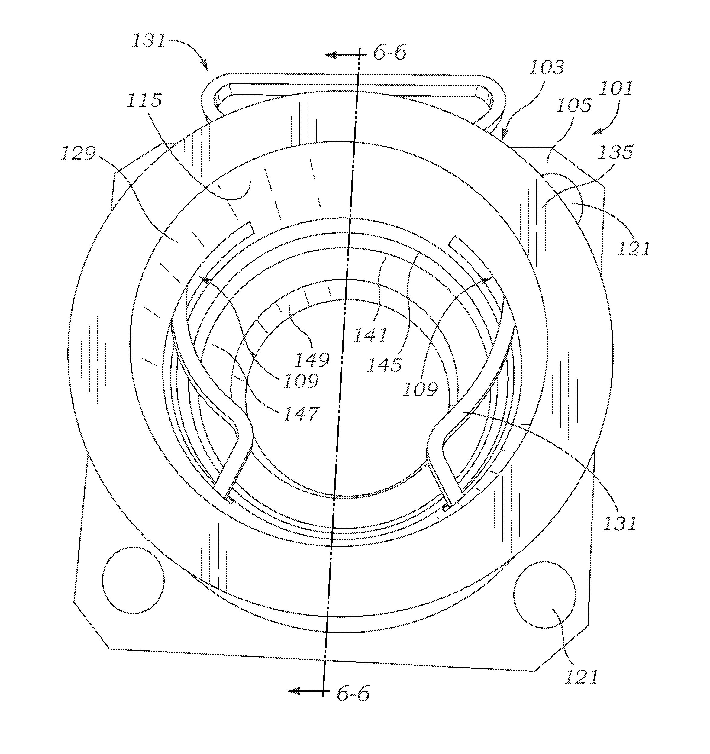
[0046]Referring to FIG. 7, a lightweight quick connector is seen as a double female quick connector 201. The numbering convention used for lightweight quick connector 101 will be preserved for all subsequently shown embodiments except for changed or to differentiate duplicated structures as needed for clarity. Double female quick connector 201 includes a first grooved pipe receiving structure 203 which may be integrally formed with a second grooved pipe receiving structure 205.

[0047]Both the first and second grooved pipe receiving structure 203 and 205 include an end surface 135, bore 129, internal surface 115, slot 109, o-ring groove 145, o-ring 141, stop land 147 and a flow opening 149. It may be preferable that the stop lands 147 match an internal diameter of the grooved pipe 53 to prevent pressure drop due to a change in flow cross sectional area and direction. The stop land 147 may ideally form the center of the double female quick connector 201.

[0048]Note that although the fir...

third embodiment

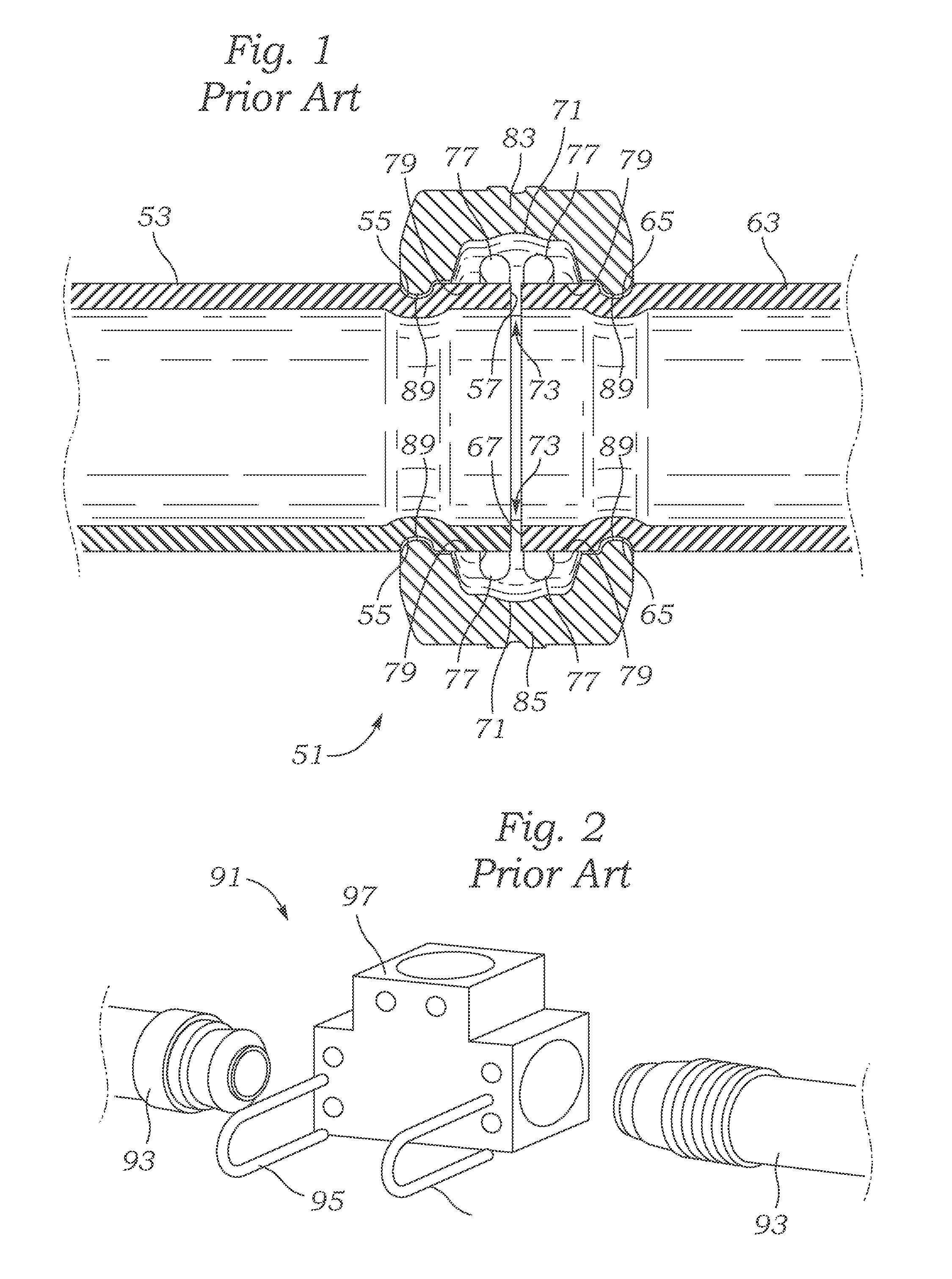
[0049]Referring to FIG. 8, a lightweight quick connector is seen as a male-female pipe size transition quick connector 231. Size transition quick connector 231 has a left side that includes a grooved pipe receiving structure 233. The stop land 147 is also provided, but has a frusto-conical transition member 235 that is either attached or integral to a grooved pipe structure 237 that is an abbreviated length of pipe that is shown as having a larger diameter than the diameter of grooved pipe 53 that would otherwise fit into bore 129. Grooved pipe structure 237, other than its being attached to the grooved pipe receiving structure 233 has the same grooved pipe end elements seen in FIG. 1, including a short segment grooved pipe 241, groove 55 and butt end 57. Thus, either the double female quick connector 201 or the a male-female pipe size transition quick connector 231 can be used to enable a pipe run to transition from one size to another.


PUM


Abstract

A lightweight quick connector system that is simpler, easier to handle, time saving structure and method for joining the ends of grooved pipe uses o-ring fluid sealing and includes a grooved pipe receiving structure for support and stabilization of the o-ring sealing structure. The quick connector system also has the capability to operate as a size adapter for either grooved pipe of different sizes and has the capability to act as a fitting adapter to enable interfitting of a grooved pipe to another size and type of pipe.

Description

BACKGROUND OF THE INVENTION[0001]1. Field of the Invention[0002]The present invention relates to high reliability lightweight quick connector system that utilizes a locking clip having curved section members for increased locking groove engagement of grooved pipe and that will save time in piping installations, especially water piping service replacing the rubber and opposing coupling systems currently used for such water distribution.[0003]2. Description of the Prior Art[0004]An industrial standard for water pipe service runs in an industrial facility has involved the use of cut groove steel and other iron pipe size “IPS” piping. Generally, for a nominal size standard, the pipe, regardless of the alloys, and for each nominal size, there is a given outside diameter that's standard, with the outside diameter never changing, but with the wall thickness and inner diameter changing for different types and materials from which the pipe is made, but generally a pipe's outer diameter does ...

Claims


Application Information

Patent Timeline
IPC IPC(8): F16L37/084F16L21/08F16L15/00F16L21/03
CPCF16L37/0841F16L15/00F16L21/08F16L21/03F16L37/144F16L15/006F16L25/009F16L25/14
Inventor BRUNELLA, ALFRED J.
Owner AP COUPLINGS INC
Why Eureka
Try Eureka