Lightweight quick connector system
a quick connector and lightweight technology, applied in the direction of couplings, screw threaded joints, pipe joints, etc., can solve the problems of significant time and effort in constructing the prior seal and coupling system, and significant weight and cost addition, etc., to achieve time-saving structure, increase the effect of locking engagement and ease of handling
- Summary
- Abstract
- Description
- Claims
- Application Information
AI Technical Summary
Benefits of technology
Problems solved by technology
Method used
Image
Examples
first embodiment
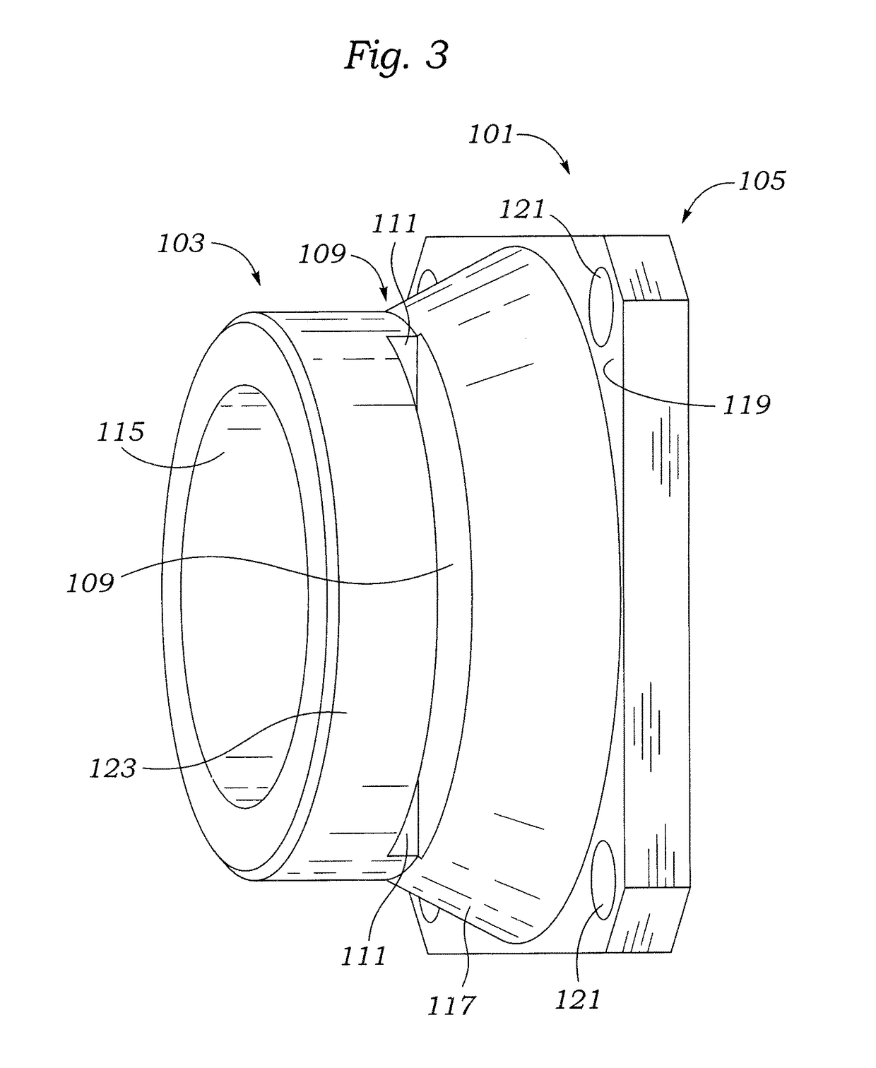
[0032]Referring to FIG. 3, a side view of a lightweight quick connector 101 is shown with one side having a grooved pipe receiving structure 103 and an opposite side having a flange 105 for bolted attachment to another structure. The quick connector 101 grooved pipe receiving structure 103 is seen to have a slot 109 that may be formed with a tangential cut through the material making up the grooved pipe receiving structure 103 and which may form exposed surfaces 111 of the material making up the grooved pipe receiving structure 103. Material behind exposed surfaces 111, which is not removed in the forming of the slots 109, regardless of how slots 109 are formed, represents the material which will determine the axial holding strength of the slots 109.
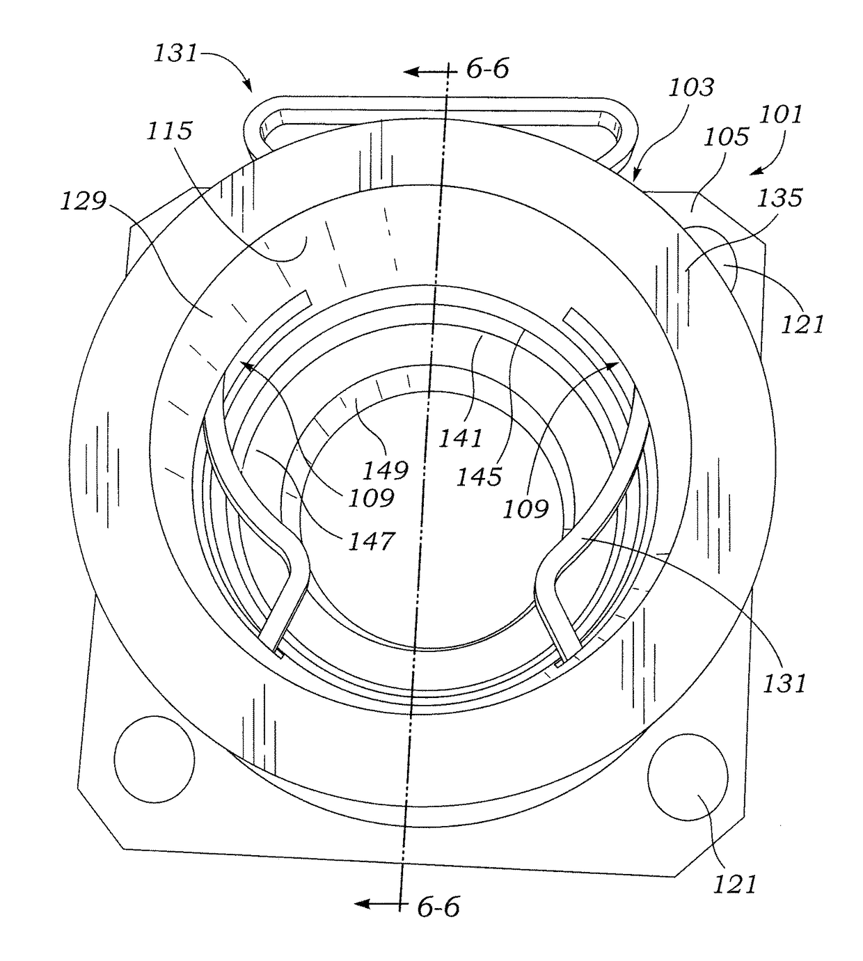
[0033]The slot 109 extends deeply enough into the material of grooved pipe receiving structure 103 that it cuts through and removes portions of the internal surface 115 of the quick connector 101. An opposite slot 109, not directly seen ...
second embodiment
[0047]Referring to FIG. 7, a lightweight quick connector is seen as a double female quick connector 201. The numbering convention used for lightweight quick connector 101 will be preserved for all subsequently shown embodiments except for changed or to differentiate duplicated structures as needed for clarity. Double female quick connector 201 includes a first grooved pipe receiving structure 203 which may be integrally formed with a second grooved pipe receiving structure 205.
[0048]Both the first and second grooved pipe receiving structure 203 and 205 include an end surface 135, bore 129, internal surface 115, slot 109, o-ring groove 145, o-ring 141, stop land 147 and a flow opening 149. It may be preferable that the stop lands 147 match an internal diameter of the grooved pipe 53 to prevent pressure drop due to a change in flow cross sectional area and direction. The stop land 147 may ideally form the center of the double female quick connector 201.
[0049]Note that although the fir...
third embodiment
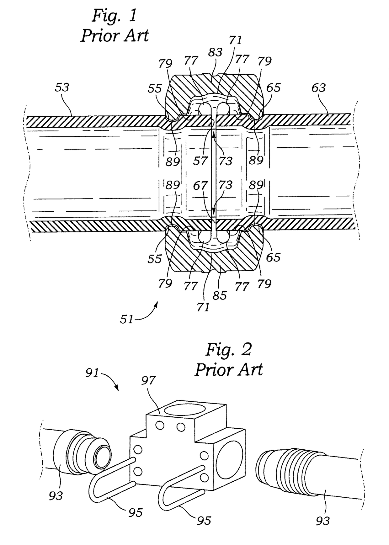
[0050]Referring to FIG. 8, a lightweight quick connector is seen as a male-female pipe size transition quick connector 231. Size transition quick connector 231 has a left side that includes a grooved pipe receiving structure 233. The stop land 147 is also provided, but has a frusto-conical transition member 235 that is either attached or integral to a grooved pipe structure 237 that is an abbreviated length of pipe that is shown as having a larger diameter than the diameter of grooved pipe 53 that would otherwise fit into bore 129. Grooved pipe structure 237, other than its being attached to the grooved pipe receiving structure 233 has the same grooved pipe end elements seen in FIG. 1, including a short segment grooved pipe 241, groove 55 and butt end 57. Thus, either the double female quick connector 201 or the a male-female pipe size transition quick connector 231 can be used to enable a pipe run to transition from one size to another.
PUM
 Abstract
Description
Claims
Application Information
 - R&D
- Intellectual Property
- Life Sciences
- Materials
- Tech Scout
- Unparalleled Data Quality
- Higher Quality Content
- 60% Fewer Hallucinations
Browse by: Latest US Patents, China's latest patents, Technical Efficacy Thesaurus, Application Domain, Technology Topic, Popular Technical Reports.
© 2025 PatSnap. All rights reserved.Legal|Privacy policy|Modern Slavery Act Transparency Statement|Sitemap|About US| Contact US: help@patsnap.com


