Method of manufacturing solid electrolytic capacitor, and solid electrolytic capacitor

a technology of solid electrolytic capacitors and manufacturing methods, applied in the manufacture of electrolytic capacitors, capacitors, basic electric elements, etc., can solve the problems of low contact resistance between the anode and the anode lead terminal, insufficient heating, and inability to manufacture solid electrolytic capacitors, etc., to achieve high reliability and high reliability

Active Publication Date: 2018-07-24
MURATA MFG CO LTD
View PDF12 Cites 1 Cited by
  • Summary
  • Abstract
  • Description
  • Claims
  • Application Information

AI Technical Summary

Benefits of technology

[0011]With the view of solving the problems described above, an object of the present invention is to provide a solid electrolytic capacitor manufacturing method capable of reliably manufacturing a solid electrolytic capacitor in which strength of bonding between an anode and an anode lead terminal is sufficient and reliability is high, and to provide the solid electrolytic capacitor, which is manufactured by that manufacturing method, and which has high reliability.
[0016]By performing the resistance increasing process by one of the above-mentioned methods, the contact resistance in the bonding portion can be reliably increased, and the anode lead terminal and the anode can be bonded to each other by the resistance welding with higher reliability. Thus, the present invention can be made more effective in practice.
[0018]With the method of manufacturing the solid electrolytic capacitor according to the preferred embodiment of the present invention, after performing the resistance increasing process on the bonding portion of the anode lead terminal with respect to the anode in order to increase the contact resistance between the anode lead terminal and the anode, the bonding portion of the anode lead terminal, the bonding portion having been subjected to the resistance increasing process, and the anode are welded to each other by the resistance welding. Therefore, electrical resistance during the resistance welding can be increased. As a result, the amount of heat generated in the bonding portion is increased and reliable resistance welding is performed, whereby stable bonding can be obtained between the anode and the anode lead terminal.
[0019]As with the method of manufacturing the solid electrolytic capacitor according to the other preferred embodiment of the present invention, when the resistance increasing process is performed on the bonding portion of the anode with respect to the anode lead terminal in order to increase the contact resistance between the anode and the anode lead terminal, and thereafter the bonding portion of the anode, the bonding portion having been subjected to the resistance increasing process, and the anode lead terminal are welded to each other by the resistance welding, it is also possible to increase electrical resistance during the resistance welding, and to increase the amount of heat generated in the bonding portion. As a result, stable bonding can be obtained between the anode and the anode lead terminal.
[0020]As with the method of manufacturing the solid electrolytic capacitor according to the still other preferred embodiment of the present invention, when the resistance increasing process is performed on each of the bonding portion of the anode with respect to the anode lead terminal and the bonding portion of the anode with respect to the anode lead terminal in order to increase the contact resistance between the anode and the anode lead terminal, and thereafter the bonding portion of the anode lead terminal and the bonding portion of the anode, the bonding portions having been subjected to the resistance increasing process, are welded to each other by the resistance welding, it is possible to more reliably increase electrical resistance during the resistance welding, and to increase the amount of heat generated in the bonding portion. As a result, even stable bonding can be obtained between the anode and the anode lead terminal.
[0021]With the solid electrolytic capacitor according to the still other preferred embodiment of the present invention, since the solid electrolytic capacitor is manufactured by the method of manufacturing the solid electrolytic capacitor according to the preferred embodiment of the present invention, a highly reliable solid electrolytic capacitor can be provided in which the anode and the anode lead terminal are reliably bonded to each other.

Problems solved by technology

In the solid electrolytic capacitor having the above-described structure disclosed in Japanese Unexamined Patent Application Publication No. 2003-124074, however, when trying to weld the connecting portion (anode lead pin) 111a of the anode 111 and the anode lead terminal 131 to each other by the resistance welding method that is widely used as a general technique, if contact resistance between the anode and the anode lead terminal is low, sufficient heating would not be obtained, and a difficulty would be caused in reliably bonding the anode lead terminal and the anode to each other.
This may lead to the problem that the anode lead terminal and the anode are not bonded to each other in some cases (i.e., a bonding failure), or that the anode lead terminal may be dropped (peeled) from the anode due to insufficient bonding strength during a later manufacturing step or during actual use as a product.
Therefore, the contact resistance between the anode and the anode lead terminal tends to lower, and the above-mentioned problem is more apt to occur.
However, if the energy during the resistance welding is too large, another problem arises in that an incidence of the so-called splash failure, i.e., scattering of metal to the surroundings, increases.

Method used


Image

  • Method of manufacturing solid electrolytic capacitor, and solid electrolytic capacitor
  • Method of manufacturing solid electrolytic capacitor, and solid electrolytic capacitor
  • Method of manufacturing solid electrolytic capacitor, and solid electrolytic capacitor

Examples


Embodiment Construction

[0029]A method of manufacturing a solid electrolytic capacitor, according to one preferred embodiment of the present invention, will be described in detail below in connection with an exemplary embodiment of the present invention.

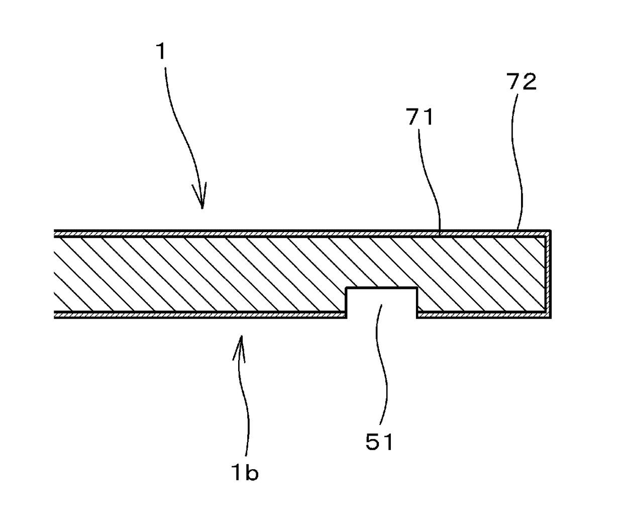
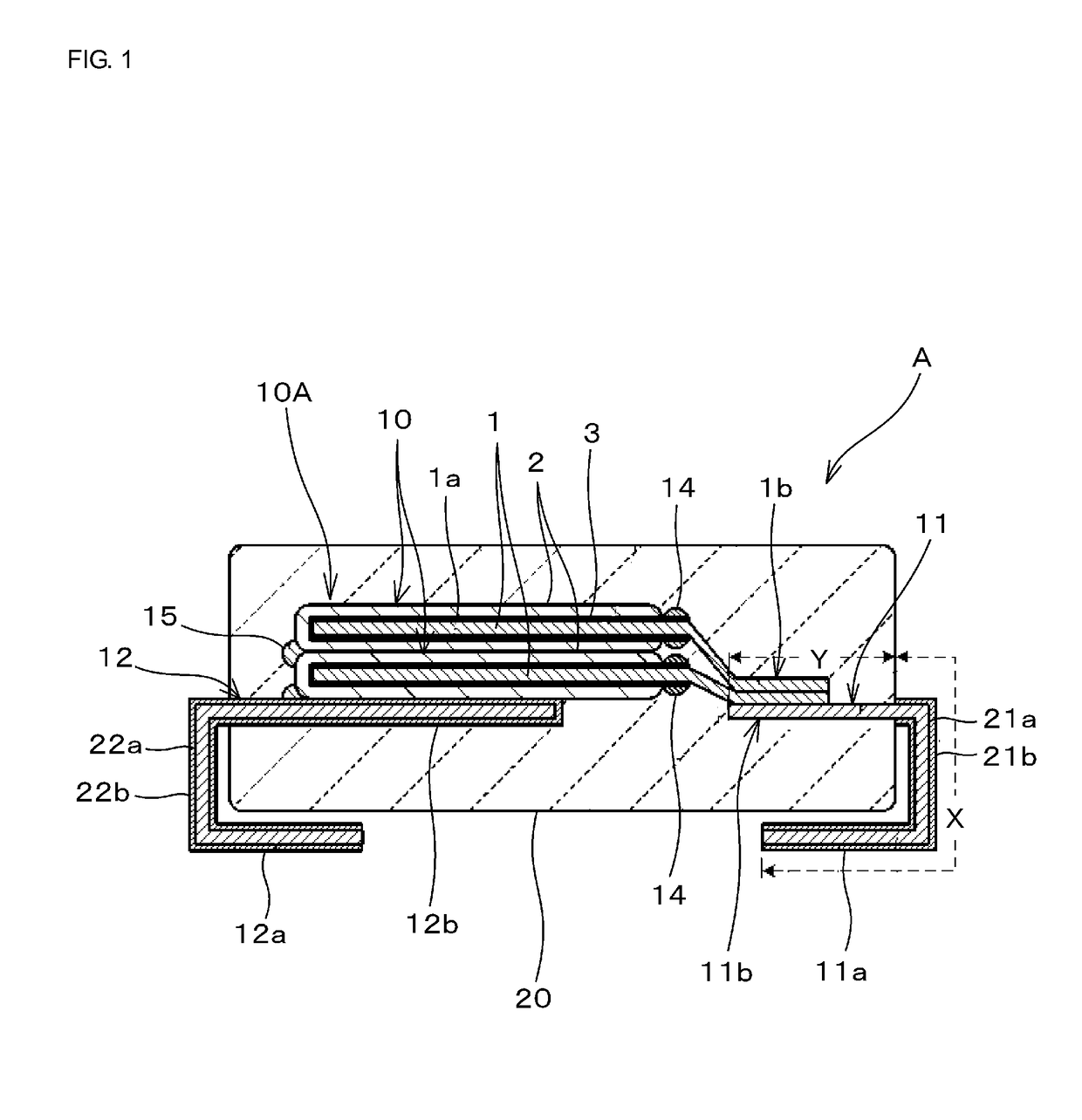
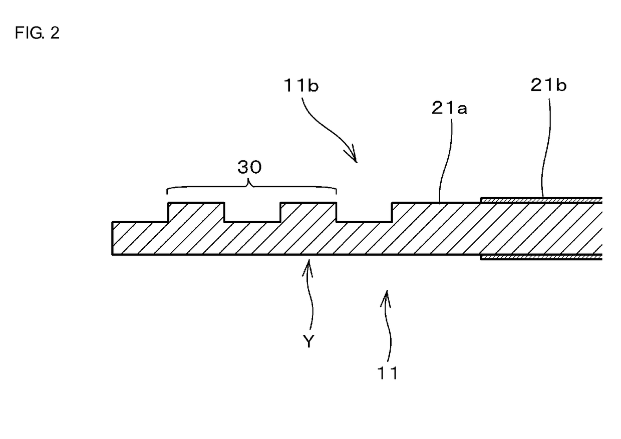
[0030]A solid electrolytic capacitor A manufactured in this embodiment includes, as illustrated in FIG. 1, two capacitor elements 10 each including an anode 1, a dielectric layer 3 disposed on the anode 1, and a cathode 2 disposed on the dielectric layer 3, an anode lead terminal 11 bonded for electrical connection to the anode 1 of the capacitor element 10, a cathode lead terminal 12 bonded for electrical connection to the cathode 2 of the capacitor element 10, and an outer coating resin 20 that covers a multilayer body 10A made up of the two capacitor elements 10 stacked one above the other, a bonding portion of the anode lead terminal 11 with respect to the anode 1 and thereabout, and a bonding portion of the cathode lead terminal 12 with respect to the ...


PUM

PropertyMeasurementUnit
thicknessaaaaaaaaaa
timeaaaaaaaaaa
thicknessaaaaaaaaaa

Abstract

A method of manufacturing a solid electrolytic capacitor wherein a resistance increasing process is performed on at least one of a bonding portion of an anode lead terminal and a bonding portion of an anode in order to increase contact resistance between the anode lead terminal and the anode. Thereafter, the anode and the anode lead terminal are welded to each other by resistance welding at the bonding portions.

Description

BACKGROUND OF THE INVENTION[0001]Field of the Invention[0002]The present invention relates to a method of manufacturing a solid electrolytic capacitor, and to the solid electrolytic capacitor. More particularly, the present invention relates to a method of manufacturing a solid electrolytic capacitor having a structure that an anode lead terminal is bonded to an anode of a capacitor element by the resistance welding method, and further relates to the solid electrolytic capacitor.[0003]Description of the Related Art[0004]As illustrated in FIG. 6, one type of related-art solid electrolytic capacitor 1 includes a capacitor element 120 including an anode (anode member) 111, a dielectric layer 112 disposed on the anode 111, and a cathode 115 disposed opposite to the anode 111 with the dielectric layer 112 interposed therebetween, an anode lead terminal 131 connected to the anode 111 of the capacitor element 120, and a cathode lead terminal 132 connected to the cathode 115, wherein the so...

Claims


Application Information

Patent Timeline
Patent Type & Authority Patents(United States)
IPC IPC(8): H01G9/15H01G9/012H01G9/14H01G9/00
CPCH01G9/15H01G9/0029H01G9/14H01G9/012Y10T29/42
Inventor MATSUBARA, TAKAHARUSHIKO, MASAMICHIKASAHARA, DAISUKE
Owner MURATA MFG CO LTD
Why Eureka
Try Eureka