Electronic device having a pivotable electrical connector, and electrical connector assembly

a technology of electrical connectors and electrical connectors, which is applied in the direction of flexible/turnable line connectors, coupling device connections, electric discharge lamps, etc., can solve the problems of difficult to connect electrically and securely each electrical connector to a respective connecting port, and the inability to avoid wire entanglemen

Inactive Publication Date: 2007-02-06
HUANG YEA YEN
View PDF6 Cites 80 Cited by
  • Summary
  • Abstract
  • Description
  • Claims
  • Application Information

AI Technical Summary

Benefits of technology

[0015]a second positioning unit disposed between said coupling end portion of the other one of said connector housing of said electrical connector and said main housing and said second pivot end of said pivot member for positioning the other one of said connector housing of said electrical connector and said main housing relative to said pivot member so as to prevent relative rotation between said pivot member and the other one of said connector housing of said electrical connector and said main housing about the second axis.
[0023]a second positioning unit disposed between the coupling end portion of the second housing of the second electrical connector and the pivot end of the second pivot member for positioning the second pivot member relative to the second housing of the second electrical connector so as to prevent relative rotation between the second electrical connector and the second pivot member about the third axis; and
[0024]a third positioning unit disposed between the coupling ends of the first and second pivot members for positioning the second pivot member relative to the first pivot member so as to prevent relative rotation between the first and second pivot members about the second axis.

Problems solved by technology

When a personal computer is placed in a limited space (e.g., the computer housing is disposed adjacent to a wall), it is difficult to connect electrically and securely each electrical connector to a respective connecting port.
Furthermore, wire entanglement cannot be avoided.

Method used


Image

  • Electronic device having a pivotable electrical connector, and electrical connector assembly
  • Electronic device having a pivotable electrical connector, and electrical connector assembly
  • Electronic device having a pivotable electrical connector, and electrical connector assembly

Examples


Embodiment Construction

[0049]Before the present invention is described in greater detail, it should be noted that like elements are denoted by the same reference numerals throughout the disclosure.

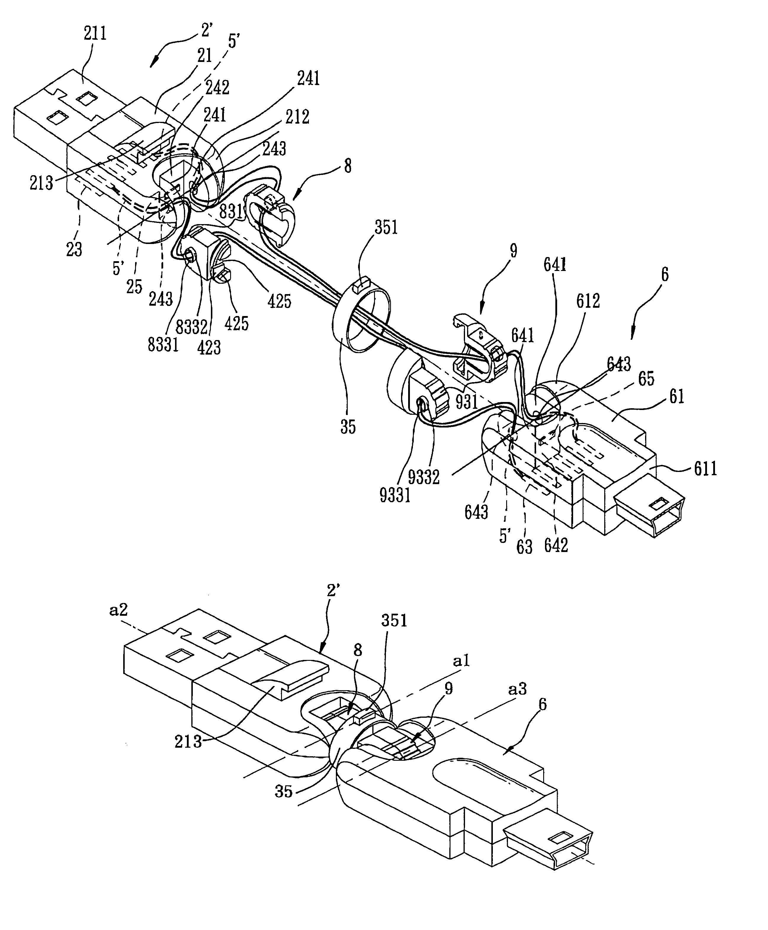
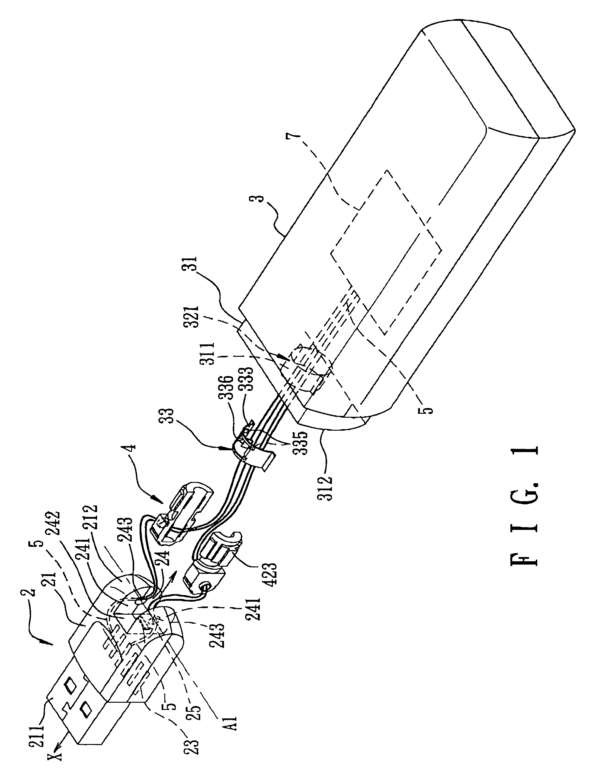
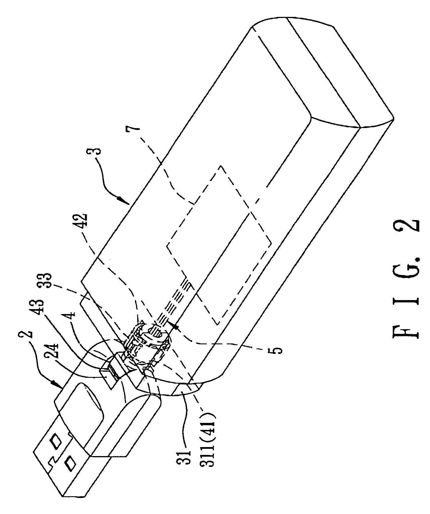
[0050]Referring to FIGS. 1 and 2, an electronic device according to the first preferred embodiment of the present invention is shown to include a main housing 3, an electrical connector 2, a hollow pivot member 4, a wire unit 5, a first positioning unit, and a second positioning unit.

[0051]The main housing 3 is housed with a circuit unit 7, and has a coupling end portion 31 formed with an opening unit that is composed of a pivot hole 311. In this embodiment, the main housing 3 is composed of a pair of complementary housing parts. The circuit unit 7 can function as a card reader, a hub or a wireless network card.

[0052]The electrical connector 2 can be in the form of a USB connector, and includes a connector housing 21 and a conductive terminal unit 23. The connector housing 21 has an insertion end portion 211, an...


PUM


Abstract

An electronic device includes a hollow pivot member interconnecting a main housing and a connector housing of an electrical connector such that the pivot member is rotatable relative to the electrical connector about a first axis and relative to main housing about a second axis perpendicular to the first axis, and a wire unit extending from the connector housing through the pivot member and into the main housing and interconnecting electrically a conductive terminal unit of the electrical connector and a circuit unit in the main housing. Relative rotation between the pivot member and the connector housing about the first axis is prevented by a first positioning unit. Relative rotation between the pivot member and the main housing about the second axis is prevented by a second positioning unit.

Description

CROSS-REFERENCE TO RELATED APPLICATION[0001]This application claims priority of Taiwanese Application No. 094101543, filed on Jan. 19, 2005.BACKGROUND OF THE INVENTION[0002]1. Field of the Invention[0003]The invention relates to an electronic device and electrical connector assembly, more particularly to an electronic device and electrical connector assembly including a pivotable electrical connector.[0004]2. Description of the Related Art[0005]A personal computer is usually mounted with a plurality of connecting ports, each of which can be connected electrically to a corresponding peripheral device by means of a corresponding electrical connector, such as a USB connector, an IEEE connector or a PS2 connector. When a personal computer is placed in a limited space (e.g., the computer housing is disposed adjacent to a wall), it is difficult to connect electrically and securely each electrical connector to a respective connecting port. Furthermore, wire entanglement cannot be avoided.S...

Claims


Application Information

Patent Timeline
Patent Type & Authority Patents(United States)
IPC IPC(8): H01R39/00
CPCH01R35/00H01R35/04
Inventor HUANG, YEA-YEN
Owner HUANG YEA YEN
Why Eureka
Try Eureka